NETA ATS
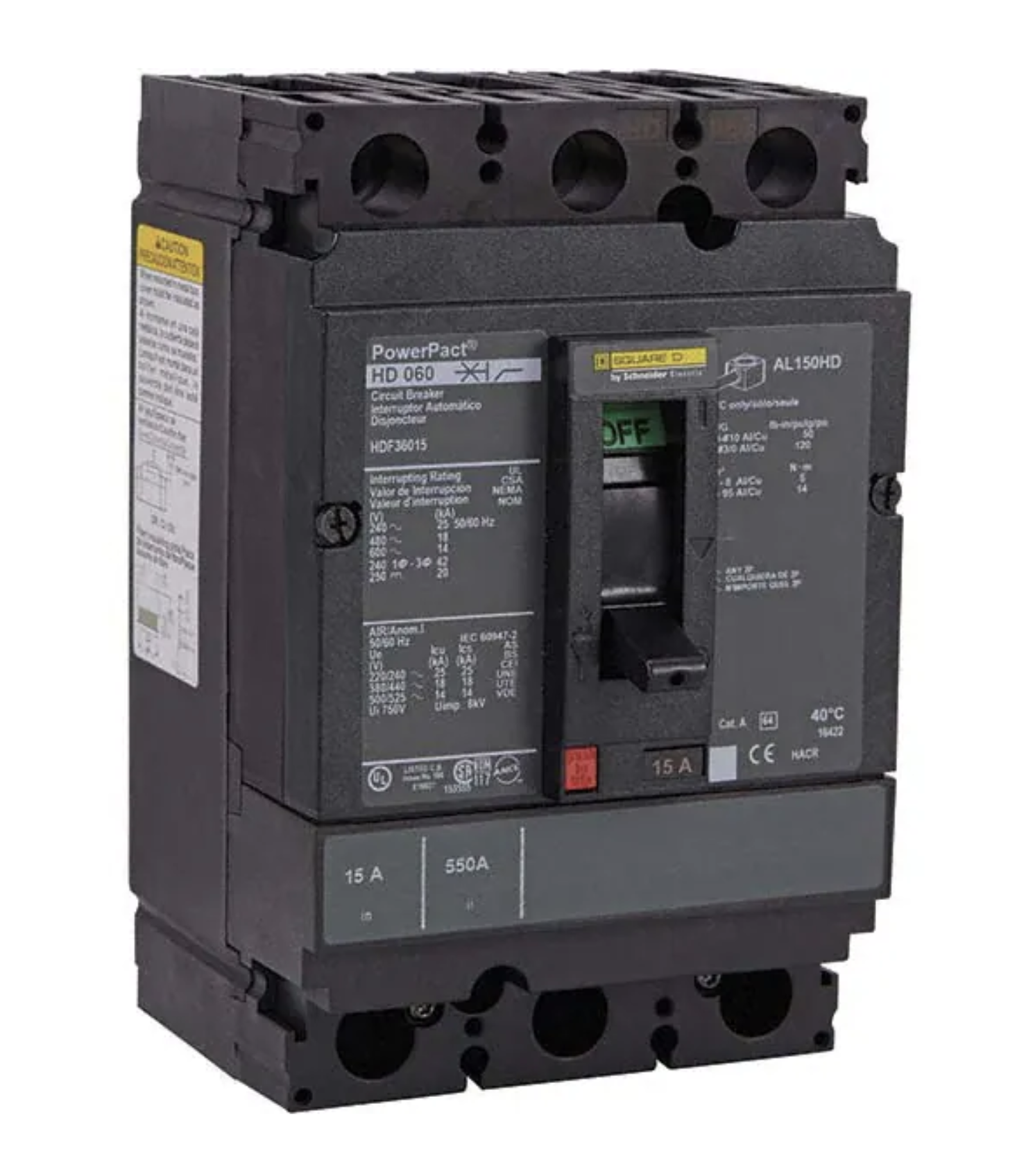
7.6.1.1 Circuit
Breakers, Air,
Insulated-Case/Molded-Case
A. Visual and Mechanical
Inspection:
- Compare equipment nameplate data with drawings and specifications.
- Inspect physical and mechanical condition.
- Inspect anchorage and alignment.
- Verify the unit is clean.
- Operate the circuit breaker to insure smooth operation.
- Inspect bolted electrical connections for high resistance using one or more of the following
methods:
- Use of a low-resistance ohmmeter in accordance with Section 7.6.1.1.B.1.
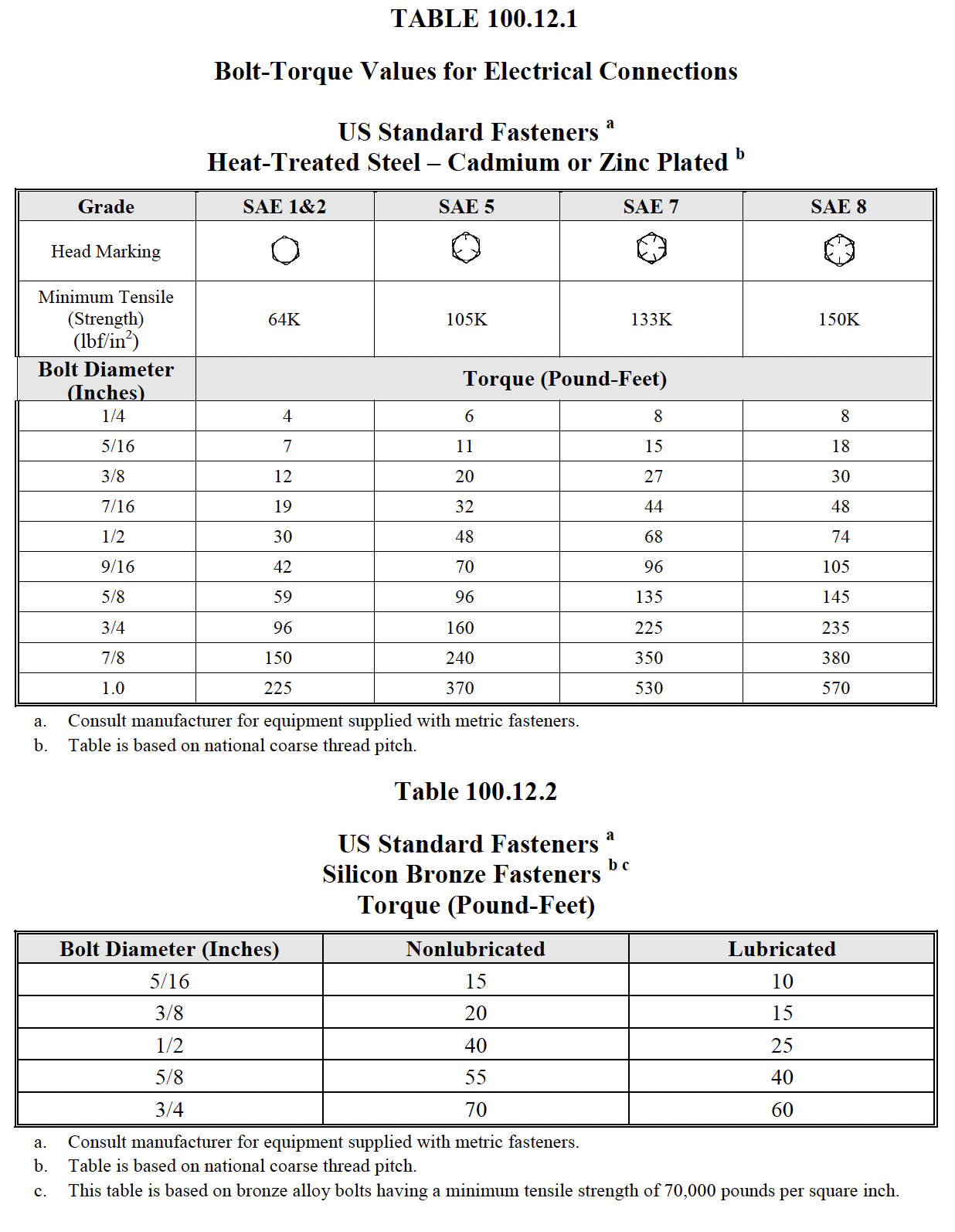
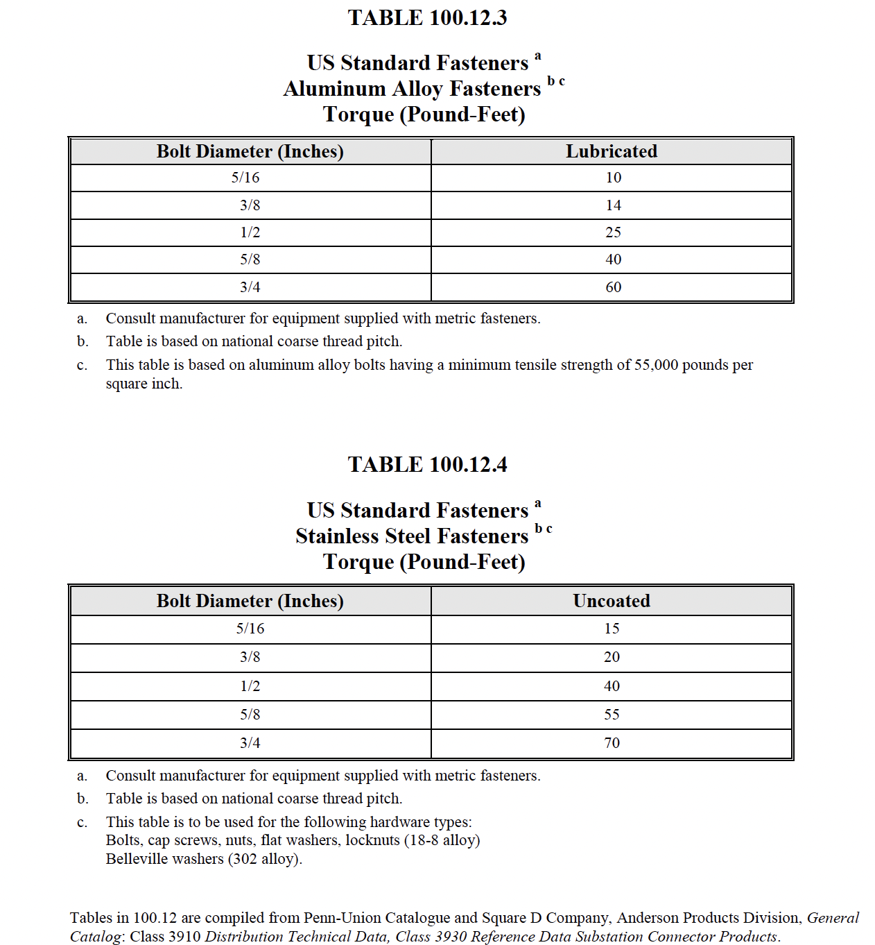
- Verify tightness of accessible bolted electrical connections by calibrated torquewrench
method in accordance with manufacturer’s published data or Table 100.12.
- Perform thermographic survey in accordance with Section 9. (optional)
- Inspect operating mechanism, contacts, and arc chutes in unsealed units.
- Perform adjustments for final protective device settings in accordance with the coordination
study.
B. Electrical Tests:
- Perform resistance measurements through bolted connections with a low-resistance
ohm meter, if applicable, in accordance with Section 7.6.1.1.A.6.1.
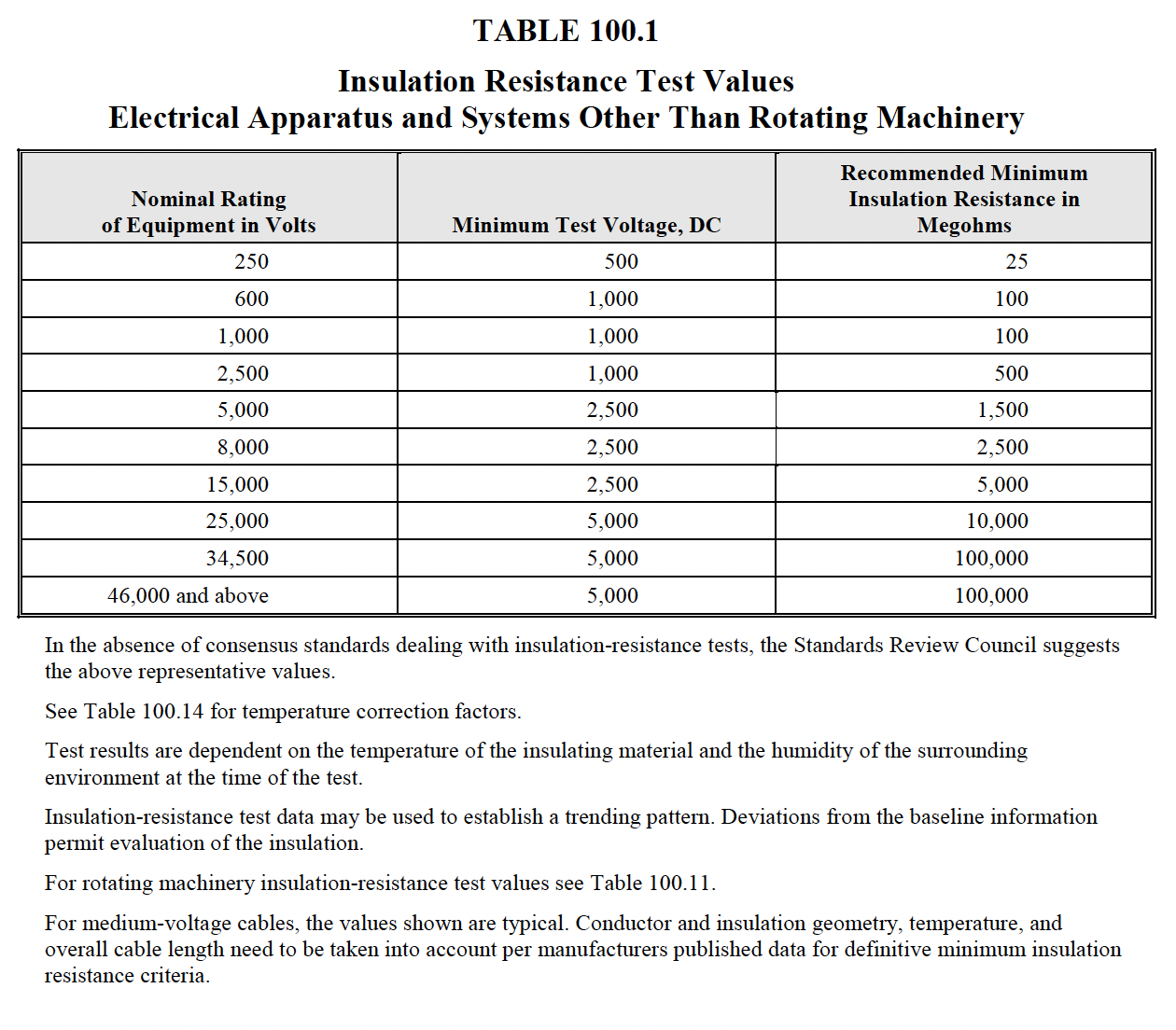
- Perform insulation-resistance tests for one minute on each pole, phase-to-phase and phase-toground
with the circuit breaker closed, and across each open pole. Apply voltage in
accordance with manufacturer’s published data. In the absence of manufacturer’s published
data, use Table 100.1.
- Perform a contact/pole-resistance test.
- Perform insulation-resistance tests on all control wiring with respect to ground. Applied
potential shall be 500 volts dc for 300-volt rated cable and 1000 volts dc for 600-volt rated
cable. Test duration shall be one minute. For units with solid-state components, follow
manufacturer’s recommendation. (optional)
- Determine long-time pickup and delay by primary current injection.
- Determine short-time pickup and delay by primary current injection.
- Determine ground-fault pickup and time delay by primary current injection.
- Determine instantaneous pickup by primary current injection.
- Test functions of the trip unit by means of secondary injection. (optional)
- Perform minimum pickup voltage tests on shunt trip and close coils in accordance with
manufacturer’s published data.
- Verify correct operation of auxiliary features such as trip and pickup indicators, zone
interlocking, electrical close and trip operation, trip-free, anti-pump function, and trip unit
battery condition. Reset all trip logs and indicators.
- Verify operation of charging mechanism.
C. Test Values – Visual and
Mechanical
- Compare bolted connection resistance values to values of similar connections. Investigate
values which deviate from those of similar bolted connections by more than 50 percent of the
lowest value.
- Bolt-torque levels shall be in accordance with manufacturer’s published data. In the absence
of manufacturer’s published data, use Table 100.12.
- Results of the thermographic survey shall be in accordance with Section 9. (optional)
- Settings shall comply with coordination study recommendations.
D. Test Values – Electrical
- Compare bolted connection resistance values to values of similar connections. Investigate
values which deviate from those of similar bolted connections by more than 50 percent of
the lowest value.
- Insulation-resistance values shall be in accordance with manufacturer’s published data. In the
absence of manufacturer’s published data, use Table 100.1. Values of insulation resistance
less than this table or manufacturer’s recommendations should be investigated.
- Micro-ohm or dc mill-ivolt drop values shall not exceed the high levels of the normal range as
indicated in the manufacturer’s published data. If manufacturer’s published data is not
available, investigate values that deviate from adjacent poles or similar breakers by more than
50 percent of the lowest value.
- Insulation-resistance values of control wiring shall not be less than two megohms.
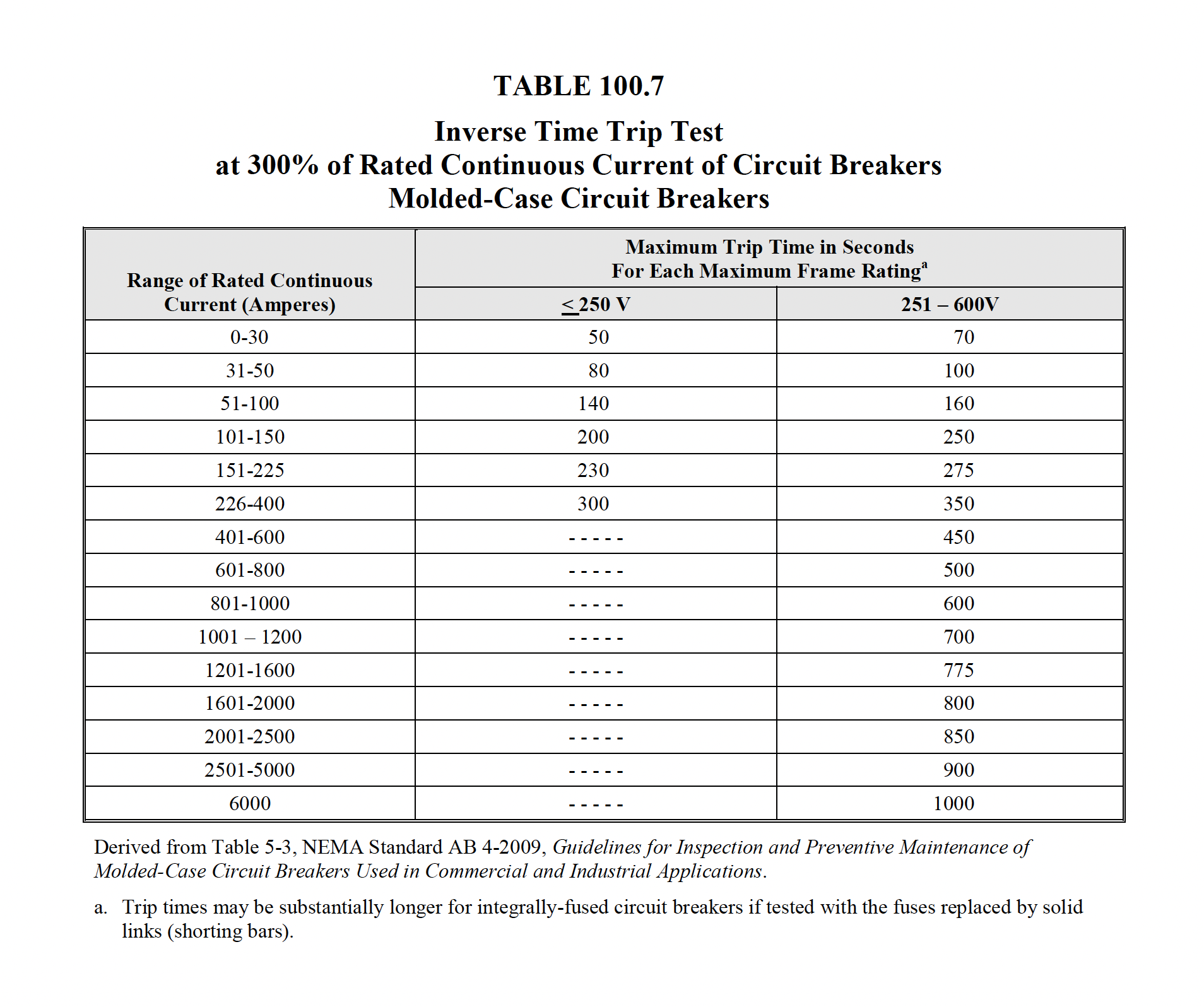
- Long-time pickup values shall be as specified, and the trip characteristic shall not exceed
manufacturer’s published time-current characteristic tolerance band, including adjustment
factors. If manufacturer’s curves are not available, trip times shall not exceed the value
shown in Table 100.7.
- Short-time pickup values shall be as specified, and the trip characteristic shall not exceed
manufacturer’s published time-current tolerance band.
- Ground fault pickup values shall be as specified, and the trip characteristic shall not exceed
manufacturer’s published time-current tolerance band.
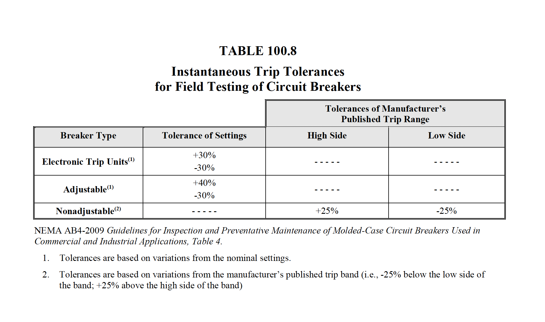
- Instantaneous pickup values shall be as specified and within manufacturer’s published
tolerances. In the absence of manufacturer’s published data, refer to Table 100.8.
- Pickup values and trip characteristics shall be within manufacturer’s published tolerances.
- Minimum pickup voltage of the shunt trip and close coils shall conform to the manufacturer’s
published data. In the absence of the manufacturer’s published data, refer to Table 100.20.
- Breaker open, close, trip, trip-free, anti-pump, and auxiliary features shall function as
designed.
- The charging mechanism shall operate in accordance with manufacturer’s published data.
NETA ATS
7.6.1.2 Circuit
Breakers, Low-Voltage Power
A. Visual and Mechanical
Inspection:
- Compare equipment nameplate data with drawings and specifications.
- Inspect physical and mechanical condition.
- Inspect anchorage, alignment, and grounding.
- Verify that all maintenance devices are available for servicing and operating the breaker.
- Verify the unit is clea
- Verify the arc chutes are intact.
- Inspect moving and stationary contacts for condition and alignment.
- Verify that primary and secondary contact wipe and other dimensions vital to satisfactory
operation of the breaker are correct.
- Perform all mechanical operator and contact alignment tests on both the breaker and its
operating mechanism in accordance with manufacturer’s published data.
- Inspect bolted electrical connections for high resistance using one or more of the following
methods:
- Use of a low-resistance ohmmeter in accordance with Section 7.6.1.2.B.1.
- Verify tightness of accessible bolted electrical connections by calibrated torquewrench
method in accordance with manufacturer’s published data or Table 100.12.
- Perform a thermographic survey in accordance with Section 9. (optional)
- Verify cell fit and element alignment.
- Verify racking mechanism operation.
- Verify appropriate lubrication on moving current-carrying parts and on moving and sliding
surfaces.
- Perform adjustments for final protective device settings in accordance with coordination
study provided by end user.
- Record as-found and as-left operation counter readings.
B. Electrical Tests:
- Perform resistance measurements through bolted connections with a low-resistance
ohmmeter, if applicable, in accordance with Section 7.6.1.2.A.10.1.
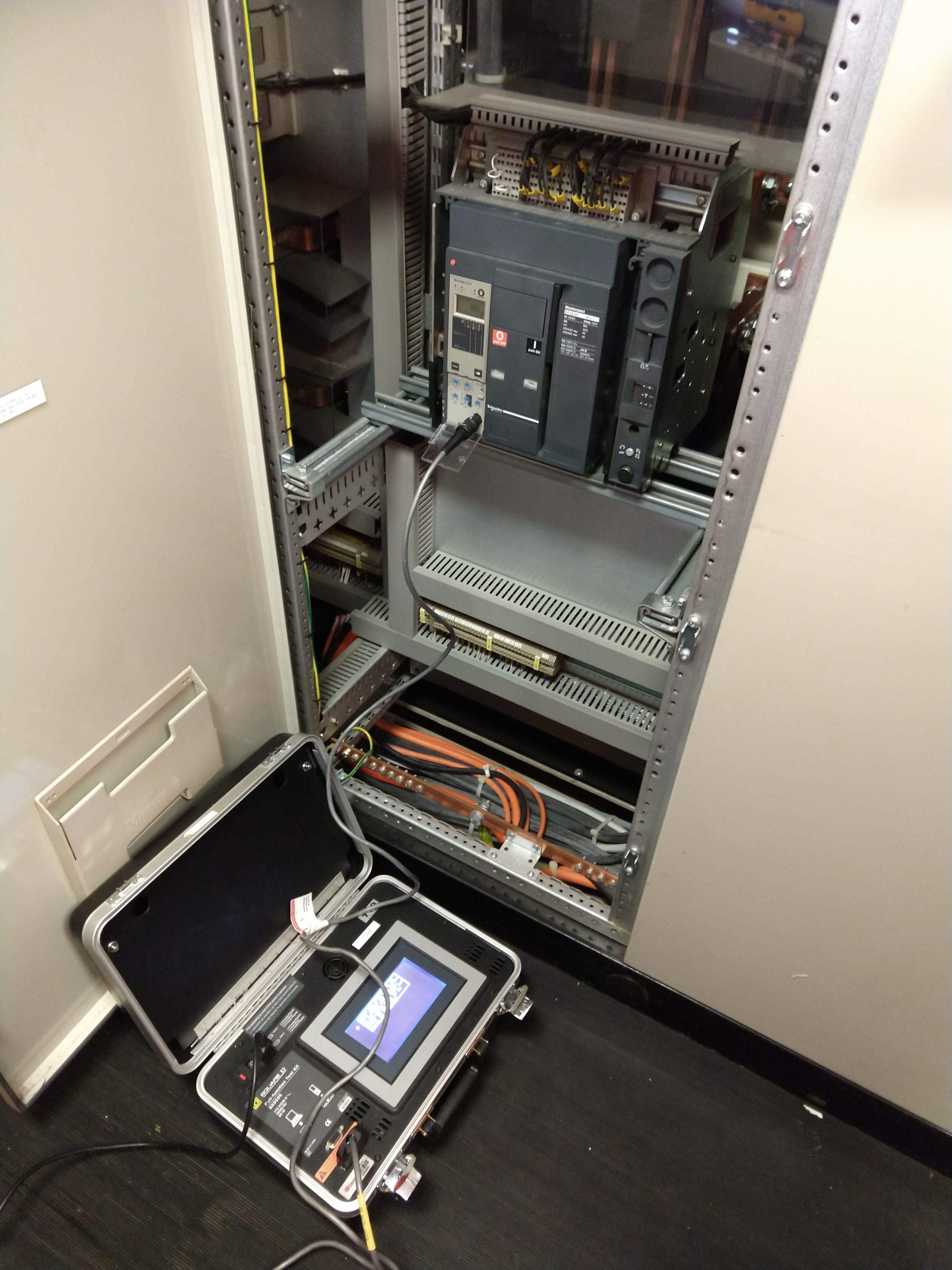
- Perform insulation-resistance tests for one minute on each pole, phase-to-phase and phase-toground
with the circuit breaker closed, and across each open pole. Test voltage shall be in
accordance with manufacturer’s published data. In the absence of manufacturer’s published
data, use Table 100.1.
- Perform a contact/pole-resistance test.
- Perform insulation-resistance tests on all control wiring with respect to ground. Applied
potential shall be 500 volts dc for 300-volt rated cable and 1000 volts dc for 600-volt rated
cable. Test duration shall be one minute. For units with solid-state components, follow
manufacturer’s recommendation.
- Determine long-time pickup and delay by primary current injection.
- Determine short-time pickup and delay by primary current injection.
- Determine ground-fault pickup and delay by primary current injection.
- Determine instantaneous pickup value by primary current injection.
- Test functions of the trip unit by means of secondary injection. (optional)
- Perform minimum pickup voltage tests on shunt trip and close coils in accordance with
manufacturer’s published data.
- Verify correct operation of any auxiliary features such as trip and pickup indicators, zone
interlocking, electrical close and trip operation, trip-free, antipump function, and trip unit
battery condition. Reset all trip logs and indicators.
- Verify operation of charging mechanism.
C. Test Values – Visual and
Mechanical
- Compare bolted connection resistance values to values of similar connections. Investigate
values which deviate from those of similar bolted connections by more than 50 percent of the
lowest value.
- Bolt-torque levels shall be in accordance with manufacturer’s published data. In the absence
of manufacturer’s published data, use Table 100.12.
- Results of the thermographic survey shall be in accordance with Section 9. (optional)
- Settings shall comply with coordination study recommendations.
- Operations counter shall advance one digit per close-open cycle.
D. Test Values – Electrical
- Compare bolted connection resistance values to values of similar connections. Investigate
values which deviate from those of similar bolted connections by more than 50 percent of
the lowest value.
- Insulation-resistance values of circuit breakers shall be in accordance with manufacturer’s
published data. In the absence of manufacturer’s published data, use Table 100.1. Values of
insulation resistance less than this table or manufacturer’s recommendations should be
investigated.
- Micro-ohm or dc milli-volt drop values shall not exceed the high levels of the normal range as
indicated in the manufacturer’s published data. In the absence of manufacturer’s published
data, investigate values that deviate from adjacent poles or similar breakers by more than 50
percent of the lowest value
- Insulation-resistance values of control wiring shall not be less than two megohms.
- Long-time pickup values shall be as specified, and the trip characteristic shall not exceed
manufacturer’s published time-current characteristic tolerance band, including adjustment
factors. If manufacturer’s curves are not available, trip times shall not exceed the value
shown in Table 100.7.
- Short-time pickup values shall be as specified, and the trip characteristic shall not exceed
manufacturer’s published time-current tolerance band.
- Ground fault pickup values shall be as specified, and the trip characteristic shall not exceed
manufacturer’s published time-current tolerance band.
- Instantaneous pickup values shall be as specified and within manufacturer’s published
tolerances. In the absence of manufacturer’s published data, refer to Table 100.8.
- Pickup values and trip characteristic shall be as specified and within manufacturer’s
published tolerances.
- Minimum pickup voltage of the shunt trip and close coils shall conform to the manufacturer’s
published data. In the absence of the manufacturer’s published data, refer to Table 100.20.
- Auxiliary features shall operate in accordance with manufacturer’s published data.
- The charging mechanism shall operate in accordance with manufacturer’s published data.
NETA MTS
7.6.1.1 Circuit
Breakers, Air,
Insulated-Case/Molded-Case
A. Visual and Mechanical
Inspection:
- Inspect physical and mechanical condition.
- Inspect anchorage and alignment.
- Prior to cleaning the unit, perform as-found tests, if required.
- Clean the unit.
- Operate the circuit breaker to ensure smooth operation.
- Inspect bolted electrical connections for high resistance using one or more of the following
methods:
- Use of a low-resistance ohmmeter in accordance with Section 7.6.1.1.B.1.
- Verify tightness of accessible bolted electrical connections by calibrated torque wrench
method in accordance with manufacturer’s published data or Table 100.12.
- Perform thermographic survey in accordance with Section 9. (optional)
- Inspect operating mechanism, contacts, and arc chutes in unsealed units.
- Perform adjustments for final protective device settings in accordance with coordination
study provided by end user.
- Perform as-left tests.
B. Electrical Tests:
- Perform resistance measurements through bolted connections with a low-resistance
ohm meter in accordance with Section 7.6.1.1.A.6.1.
- Perform insulation-resistance tests for one minute on each pole, phase-to-phase and phaseto-
ground with the circuit breaker closed, and across each open pole. Apply voltage in
accordance with manufacturer’s published data. In the absence of manufacturer’s published
data, use Table 100.1.
- Perform a contact/pole-resistance test.
- Perform insulation-resistance tests on all control wiring with respect to ground. The applied
potential shall be 500 volts dc for 300-volt rated cable and 1000 volts dc for 600-volt rated
cable. Test duration shall be one minute. For units with solid-state components, follow
manufacturer’s recommendation. (optional)
- Determine long-time pickup and delay by primary current injection.
- Determine short-time pickup and delay by primary current injection.
- Determine ground-fault pickup and time delay by primary current injection.
- Determine instantaneous pickup by primary current injection.
- Test functions of the trip unit by means of secondary injection. (optional)
- Perform minimum pickup voltage test on shunt trip and close coils in accordance with
Table 100.20.
- Verify correct operation of auxiliary features such as trip and pickup indicators, zone
interlocking, electrical close and trip operation, trip-free, anti-pump function, and trip unit
battery condition. Reset all trip logs and indicators.
- Reset all trip logs and indicators.
- Verify operation of charging mechanism.
C. Test Values – Visual and
Mechanical
- Compare bolted connection resistance values to values of similar connections. Investigate
values which deviate from those of similar bolted connections by more than 50 percent of
the lowest value.
- Bolt-torque levels should be in accordance with manufacturer’s published data. In the
absence of manufacturer’s published data, use Table 100.12.
- Results of the thermographic survey shall be in accordance with Section 9. (optional)
- Settings shall comply with coordination study recommendations.
D. Test Values – Electrical
- Compare bolted connection resistance values to values of similar connections. Investigate
values which deviate from those of similar bolted connections by more than 50 percent of
the lowest value.
- Insulation-resistance values should be in accordance with manufacturer’s published data. In
the absence of manufacturer’s published data, use Table 100.1. Values of insulation
resistance less than this table or manufacturer’s recommendations should be investigated.
- Micro-ohm or dc milli-volt drop values should not exceed the high levels of the normal range
as indicated in the manufacturer’s published data. If manufacturer’s data is not available,
investigate values that deviate from adjacent poles or similar breakers by more than 50
percent of the lowest value.
- Insulation-resistance values of control wiring should be comparable to previously obtained
results but not less than two mega-ohms.
- Long-time pickup values should be as specified, and the trip characteristic should not
exceed manufacturer’s published time-current characteristic tolerance band, including
adjustment factors. If manufacture
- Short-time pickup values shall be as specified, and the trip characteristic shall not exceed
manufacturer’s published time-current tolerance band.
- Ground fault pickup values shall be as specified, and the trip characteristic shall not exceed
manufacturer’s published time-current tolerance band.
- Instantaneous pickup values shall be as specified and within manufacturer’s published
tolerances. In the absence of manufacturer’s published data, refer to Table 100.8.
- Pickup values and trip characteristics shall be within manufacturer’s published tolerances.
- Minimum pickup voltage of the shunt trip and close coils shall conform to the manufacturer’s
published data. In the absence of the manufacturer’s published data, refer to Table 100.20.
- Breaker open, close, trip, trip-free, anti-pump, and auxiliary features shall function as
designed.
- Trip logs and indicators are reset.
- The charging mechanism shall operate in accordance with manufacturer’s published data.
NETA ATS
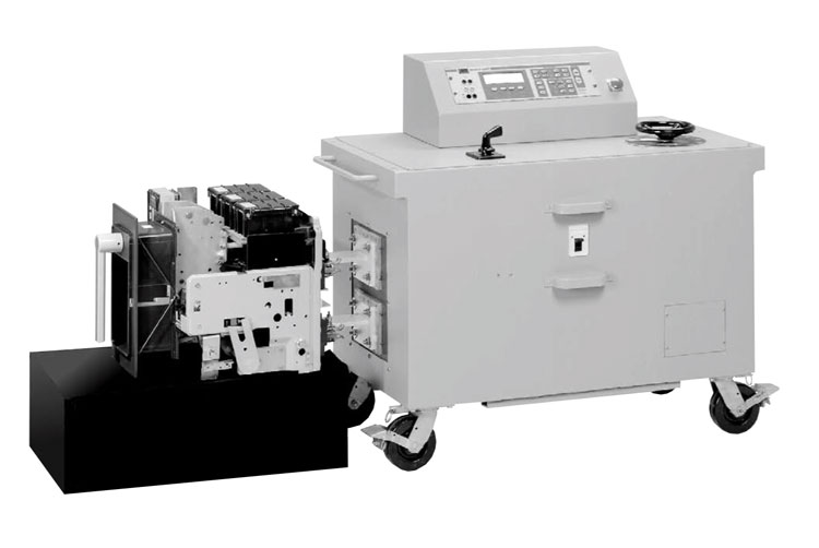
7.6.1.2 Circuit
Breakers, Low-Voltage Power
A. Visual and Mechanical
Inspection:
- Inspect physical and mechanical condition.
- Inspect anchorage, alignment, and grounding.
- Verify that all maintenance devices are available for servicing and operating the breaker.
- Prior to cleaning the unit, perform as-found tests, if required.
- Clean the unit.
- Inspect arc chutes.
- Inspect moving and stationary contacts for condition and alignment.
- Verify that primary and secondary contact wipe and other dimensions vital to satisfactory
operation of the breaker are in accordance with manufacturer’s published data.
- Perform all mechanical operator and contact alignment tests on both the breaker and its
operating mechanism in accordance with manufacturer’s published data.
- Inspect bolted electrical connections for high resistance using one or more of the following
methods:
- Use of a low-resistance ohmmeter in accordance with Section 7.6.1.2.B.1.
- Verify tightness of accessible bolted electrical connections by calibrated torque wrench
method in accordance with manufacturer’s published data or Table 100.12.
- Perform a thermographic survey in accordance with Section 9. (optional)
- Verify cell fit and element alignment.
- Verify racking mechanism operation.
- Verify appropriate lubrication on moving current-carrying parts and on moving and sliding
surfaces.
- Perform adjustments for final protective device settings in accordance with coordination
study provided by end user.
- Perform as-left tests.
- Record as-found and as-left operation counter readings.
B. Electrical Tests:
- Perform resistance measurements through bolted connections with a low-resistance
ohmmeter, if applicable, in accordance with Section 7.6.1.2.A.10.1.
- Perform insulation-resistance tests for one minute on each pole, phase-to-phase and phase-toground
with the circuit breaker closed, and across each open pole. Test voltage shall be in
accordance with manufacturer’s published data. In the absence of manufacturer’s published
data, use Table 100.1.
- Perform a contact/pole-resistance test.
- Perform insulation-resistance tests on all control wiring with respect to ground. Applied
potential shall be 500 volts dc for 300-volt rated cable and 1000 volts dc for 600-volt rated
cable. Test duration shall be one minute. For units with solid-state components, follow
manufacturer’s recommendation.
- Determine long-time pickup and delay by primary current injection.
- Determine short-time pickup and delay by primary current injection.
- Determine ground-fault pickup and delay by primary current injection.
- Determine instantaneous pickup value by primary current injection.
- Test functions of the trip unit by means of secondary injection. (optional)
- Perform minimum pickup voltage test on shunt trip and close coils in accordance with
manufacturer’s published data. In the absence of manufacturer’s published data, refer to
Table 100.20.
- Verify correct operation of auxiliary features such as trip and pickup indicators, zone
interlocking, electrical close and trip operation, trip-free, antipump function, and trip unit
battery condition.
- Reset all trip logs and indicators.
- Verify operation of charging mechanism.
C. Test Values – Visual and
Mechanical
- Compare bolted connection resistance values to values of similar connections. Investigate
values which deviate from those of similar bolted connections by more than 50 percent of the
lowest value.
- Bolt-torque levels shall be in accordance with manufacturer’s published data. In the absence
of manufacturer’s published data, use Table 100.12.
- Results of the thermographic survey shall be in accordance with Section 9. (optional)
- Settings shall comply with coordination study recommendations.
- Operations counter shall advance one digit per close-open cycle.
D. Test Values – Electrical
- Compare bolted connection resistance values to values of similar connections. Investigate
values which deviate from those of similar bolted connections by more than 50 percent of
the lowest value.
- Insulation-resistance values of circuit breakers shall be in accordance with manufacturer’s
published data. In the absence of manufacturer’s published data, use Table 100.1. Values of
insulation resistance less than this table or manufacturer’s recommendations should be
investigated.
- Micro-ohm or dc milli-volt drop values shall not exceed the high levels of the normal range as
indicated in the manufacturer’s published data. In the absence of manufacturer’s published
data, investigate values that deviate from adjacent poles or similar breakers by more than 50
percent of the lowest value
- Insulation-resistance values of control wiring shall not be less than two megohms.
- LLong-time pickup values should be as specified, and the trip characteristic shall not exceed
manufacturer’s published time-current characteristic tolerance band.
- Short-time pickup values shall be as specified, and the trip characteristic shall not exceed
manufacturer’s published time-current tolerance band.
- Ground fault pickup values shall be as specified, and the trip characteristic shall not exceed
manufacturer’s published time-current tolerance band.
- Instantaneous pickup values should be within the tolerances of manufacturer’s published
data.
- Pickup values and trip characteristic shall be as specified and within manufacturer’s
published tolerances.
- Minimum pickup voltage of the shunt trip and close coils shall conform to the manufacturer’s
published data. In the absence of the manufacturer’s published data, refer to Table 100.20.
- Auxiliary features shall operate in accordance with manufacturer’s published data.
- Trip logs and indicators are reset.
- The charging mechanism should operate in accordance with manufacturer’s published data.
NETA ATS
/ MTS
TABLE
100.1
NETA ATS
/ MTS
TABLE
100.7
NETA ATS
/ MTS
TABLE
100.8
NETA ATS
/ MTS
TABLE
100.12
NETA ATS
/ MTS
TABLE
100.20
|