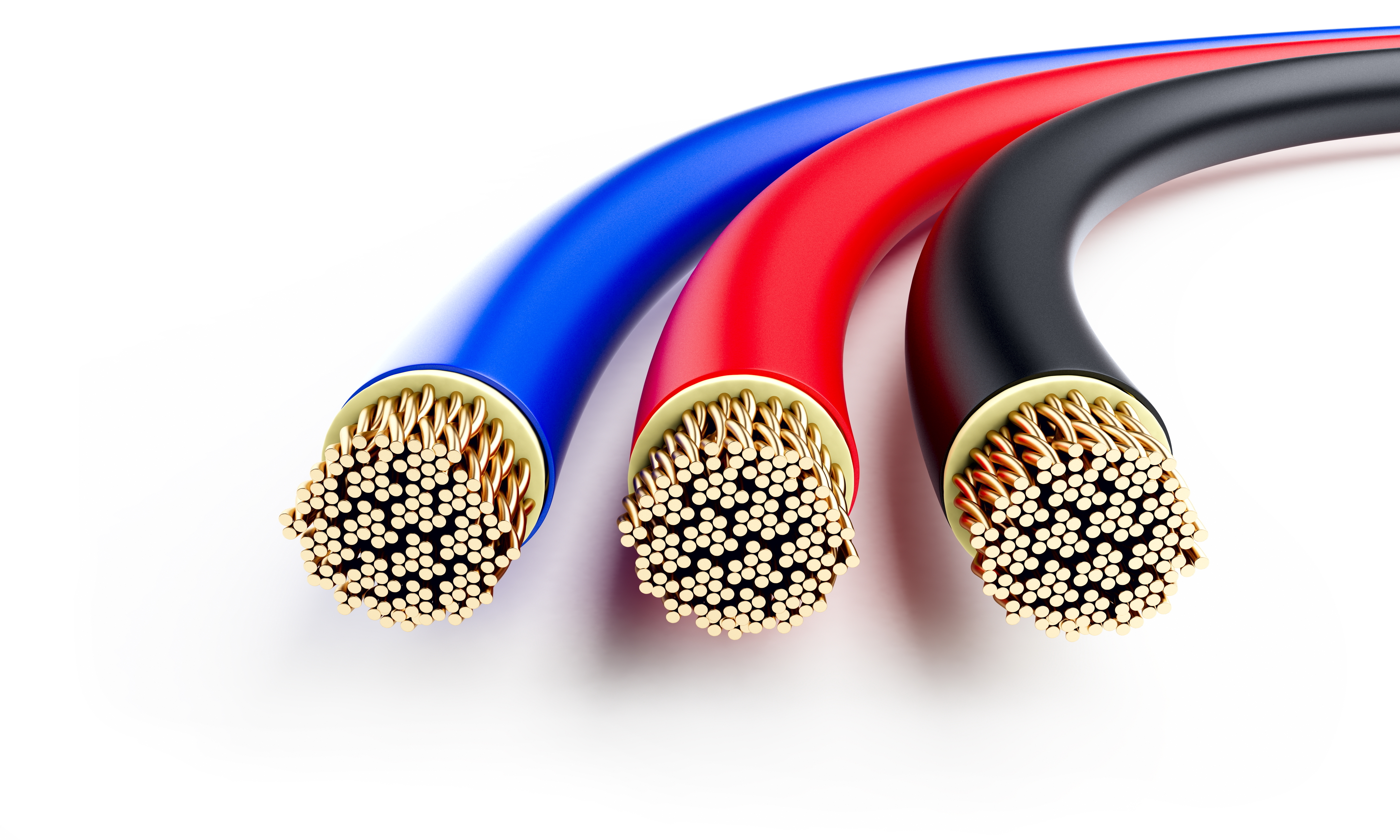
Cable Testing
Cable Insulation Resistance Test is an important procedure to assess the quality and integrity of electrical conductors. Conductors that are subjected to excessive stress or adverse environmental conditions can deteriorate over time. Regular testing can detect early signs of wear, corrosion, or other issues that may lead to failures and costly breakdowns.
Electrical cable insulation test is typically performed for the following reasons:
Installation (Acceptance Testing)
:
Insulation tests are often performed after
the
installation of new electrical cables to verify that the
insulation has been correctly installed and is free from any
initial
faults or damage. This helps identify any issues that may
have occurred during the installation process before the
system is energized.
Periodic Maintenance:
Regular
preventive maintenance
programs often include insulation testing as part of their
routine. Periodic insulation tests help assess the condition
of the insulation over time, detect any deterioration or
degradation, and identify potential insulation faults before
they cause problems or lead to system failures.
Troubleshooting:
Insulation
tests are valuable in troubleshooting electrical issues.
When there is an unexpected electrical fault, insulation
tests can help determine if insulation damage or degradation
is the cause.
By pinpointing the location and severity of insulation
problems, it becomes easier to plan repairs or replacements
accordingly.
Following Significant
Events:
Insulation tests are recommended
after significant
events that may impact the electrical system, such as power
surges, lightning strikes, equipment failures, or other
electrical disturbances.
These events can cause insulation stress or damage, and
conducting insulation tests helps assess the system's
integrity and
identify any resulting issues.
| Cable Insulation Resistance Test procedure, Low Voltage (Less than 600V) | |
|---|---|
PurposeCable testing is conducted to chart the gradual deterioration over the years, to do acceptance testing after installation, for verification of splices and joints, and for special repair testing. Acceptance Testing (New Cables)Acceptance testing is performed after the installation of all cable and accessories, but before energizing the cable with system voltage. Its purpose is to detect installation damage in both the cable and cable accessories. Maintenance TestingOver time, cable insulation will degrade. A true evaluation is based on a trend in readings over a time period. Maintenance testing is performed during the operating life of the cable system. Its purpose is to assess the condition and check the serviceability of the cable system so that suitable maintenance procedures can be initiated. Test resistance values can vary, depending upon such factors as the temperature or moisture content of the insulation (resistance decreases in temperature or moisture) Sometimes the drop in insulation resistance is sudden, as when equipment is flooded. Usually, however, it drops gradually A trend showing declining resistance values will be gradual, giving plenty of warning, of a possible service failure Typically, cables have a design life of at least 20-30 years, but various stresses can increase the natural aging process and decreasing the normal working life of the cable. Common environmental and mechanical stresses found in a plant’s electrical system are:
Test EquipmentThe insulation resistance is measured using a Megohmmeter (or it can be measured using a portable instrument consisting of a direct voltage source, such as a generator, battery, or rectifier, and a high-range ohmmeter that gives insulation resistance readings in megohms or ohms). This is a nondestructive method of determining the condition of the cable insulation to check contamination due to moisture, dirt, or carbonization. 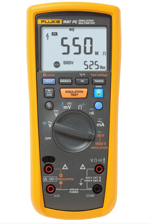
Fluke 1587 Insulation Resistance Test SetTest ProcedureVisual and Mechanical Inspection:
Insulation Test:
Applied test voltage and results should be in accordance with NETA Table 100.1. 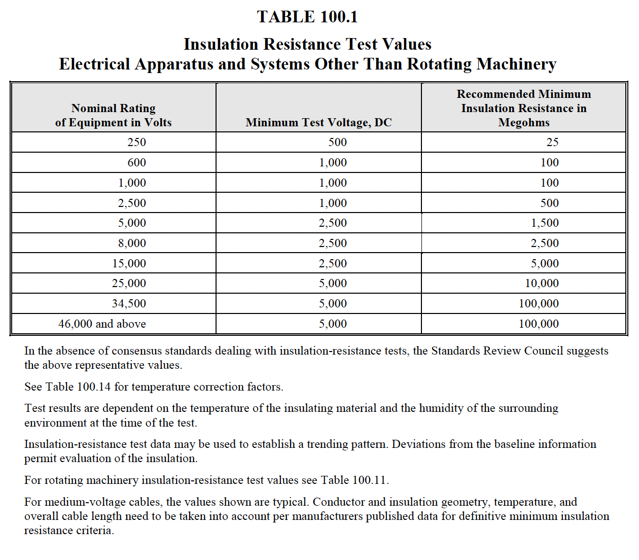
NETA Table 100.1 shows recommended minimum test result valuesTest Results
|
|
| NETA Test Procedure, Low Voltage | |
|---|---|
NETA ATS7.3.2 Cable Low-Voltage, 600-Volt MaximumA. Visual and Mechanical Inspection:
B. Electrical Tests:
C. Test Values – Visual and Mechanical
D. Test Values – Electrical
NETA MTS7.3.2 Cable Low-Voltage, 600-Volt MaximumA. Visual and Mechanical Inspection:
B. Electrical Tests:
C. Test Values – Visual and Mechanical
D. Test Values – Electrical
NETA
ATS / MTS
NETA ATS /
MTS
|
|
| Medium Voltage Cable Testing, VLF Method | ||||||||||||||||||||||||||||||||||||||||||||||||||||||||||||||||||||||||||||||||||||||||||||||||||
|---|---|---|---|---|---|---|---|---|---|---|---|---|---|---|---|---|---|---|---|---|---|---|---|---|---|---|---|---|---|---|---|---|---|---|---|---|---|---|---|---|---|---|---|---|---|---|---|---|---|---|---|---|---|---|---|---|---|---|---|---|---|---|---|---|---|---|---|---|---|---|---|---|---|---|---|---|---|---|---|---|---|---|---|---|---|---|---|---|---|---|---|---|---|---|---|---|---|---|
|
IntroductionVLF testing is considered a safe and efficient method for medium voltage cable testing. The method is used for assessing the integrity and reliability of high voltage cables. This testing method helps identify cable defects, insulation degradation, and potential weaknesses in the cable insulation. VLF testing is considered a non-destructive testing technique that can be used for both new cable installations and routine maintenance of existing cable systems. In addition, VLF testing can be performed on longer cable lengths compared to DC testing methods. Principals of VLF TestingVLF testing utilizes an alternating current (AC) source with a frequency typically in the range of 0.01 Hz to 0.1 Hz, which is much lower than the power frequency (50 Hz or 60 Hz). This low-frequency AC is applied to the cable under test, creating an electric field that stresses the insulation and reveals potential weaknesses. Test EquipmentVLF test equipment consists of a VLF high voltage source, which applies a low frequency sinusoidal waveform with the desired frequency to the cable. The test set also monitors and measures test parameters, including voltage, current, and waveforms. Test ProcedureVisual and Mechanical Inspection:
Shield-continuity and Insulation Test:
NETA Table 100.1 shows recommended minimum test result valuesVLF Test Result:
NOTE 1 - If the operating voltage is a voltage class lower than the rated voltage of the cable, it is recommended that the maintenance test voltages should be those corresponding to the operating voltage class. NOTE 2 -IEEE Guide for Field Testing of Shielded Power Cable Systems Using Very Low Frequency (VLF) The maintenance voltage is about 75% of the acceptance test voltage magnitude. NOTE 3 - Some existing test sets have a maximum voltage that is up to 5% below the values listed in the table. These test sets are acceptable to be used. However, there is a risk that the cable may be “undertested” due to a combination of lower test voltage and allowed uncertainty of the measuring circuit. VLF ac voltage testing methods utilize ac signals at frequencies in the range of 0.01 Hz to 1 Hz. The most commonly used, commercially available VLF ac voltage test frequency is 0.1 Hz. VLF ac test voltages with cosine-rectangular and the sinusoidal wave shapes are most commonly used. While other wave shapes are available for testing of cable systems, recommended test voltage levels have not been established. Fault Current CalculationsShort circuit analysis of the system model is done using SKM's A_FAULT module, which determines the maximum fault levels at each bus; typically, this would be inside switchgear and panels. The module automatically compare these values against manufacturer short circuit current ratings. A_FAULT ModuleThe module provides calculated fault values, complies with ANSI/IEEE C37 standard for fault currents calculations. The software also uses the standard's evaluation factors and ratios required for high- and low-voltage device short circuit duty evaluation. 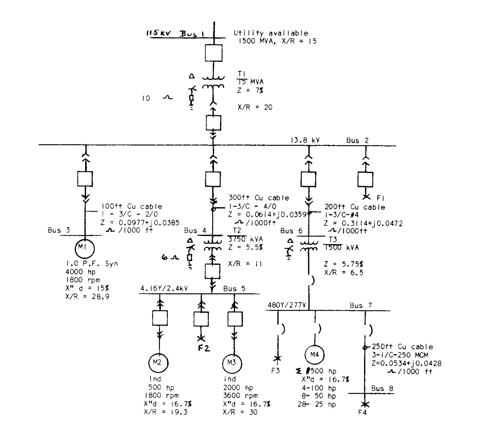
GeneralVery Low Frequency (VLF)cable testing is a widely used method for assessing the integrity and reliability of high voltage cables, such as power cables used in electrical grids. |
||||||||||||||||||||||||||||||||||||||||||||||||||||||||||||||||||||||||||||||||||||||||||||||||||
| NETA Test Procedure, Medium Voltage | |
|---|---|
NETA ATS (Acceptance)7.3.3 Cables, Medium- and High-VoltageA. Visual and Mechanical Inspection:
B. Electrical Tests:
Dielectric WithstandBaseline Diagnostic TestingC. Test Values – Visual and Mechanical
D. Test Values – Electrical
NETA MTS (Maintenance)7.3.3 Shielded Cables, Medium- and High-VoltageA. Visual and Mechanical Inspection:
B. Electrical Tests:
Due to
the various cable
testing methods
commercially
available, the
following section
does not
denote “optional” or
“required” tests. It
is only after
careful analysis of
all circuit
parameters
between the testing
entity and the cable
owner that a
preferred testing
method should be
selected.
Dielectric WithstandDiagnostic TestsC. Test Values – Visual and Mechanical
D. Test Values – Electrical
NETA ATS / MTS
TABLE
100.5
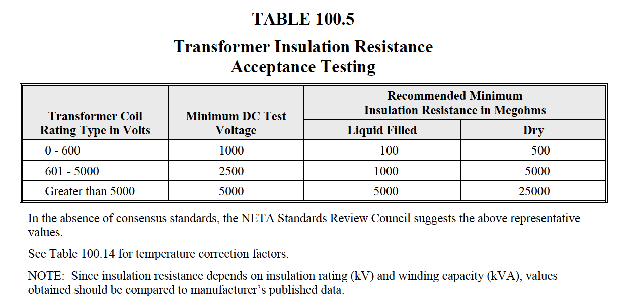
NETA
ATS / MTS
TABLE
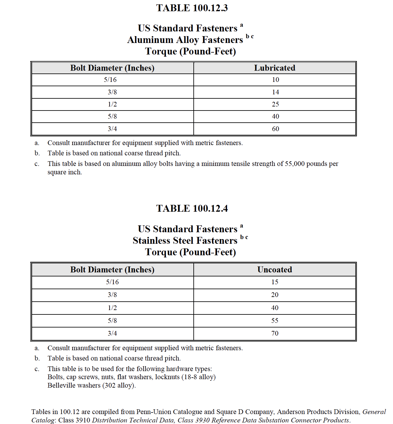
100.12
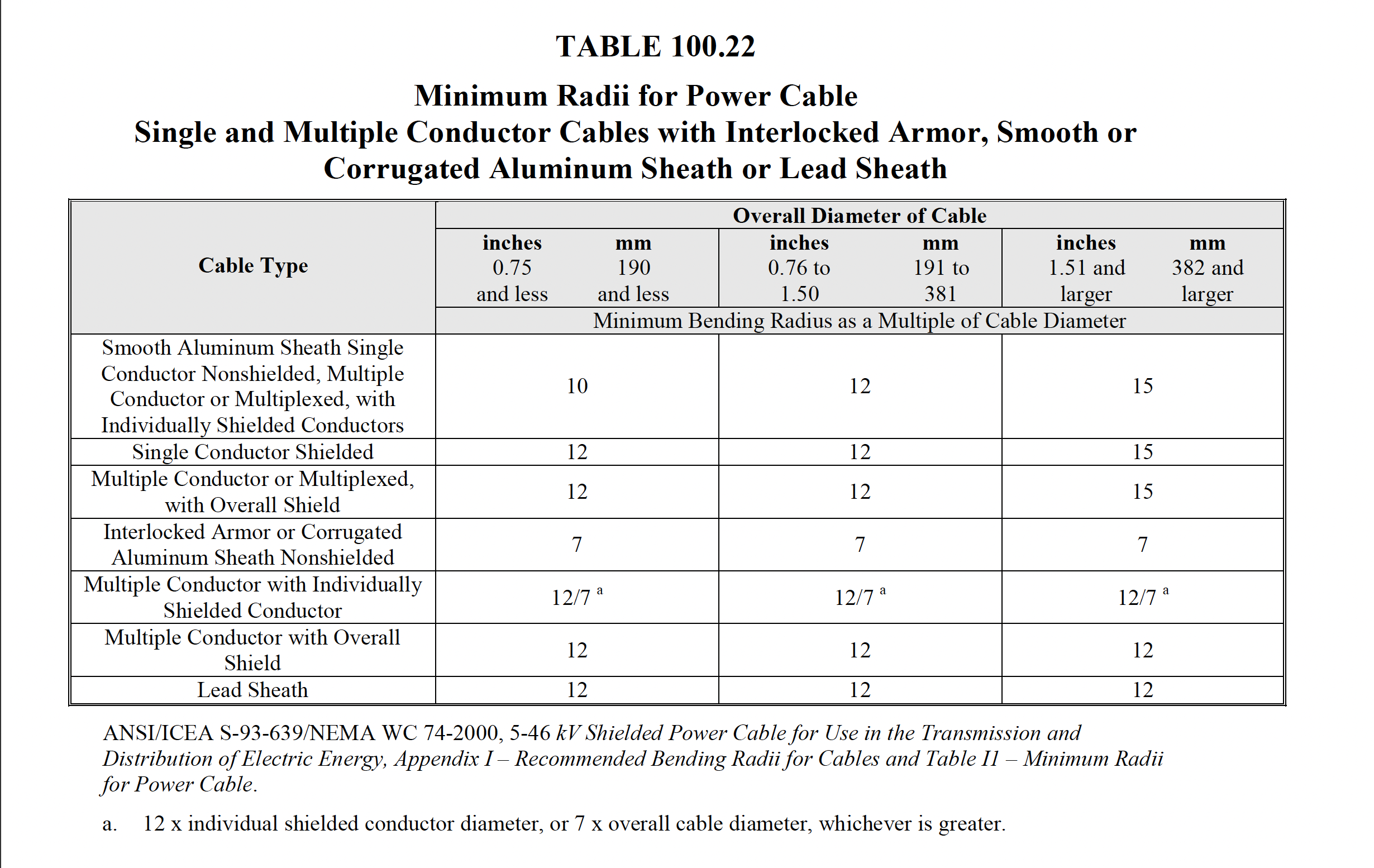
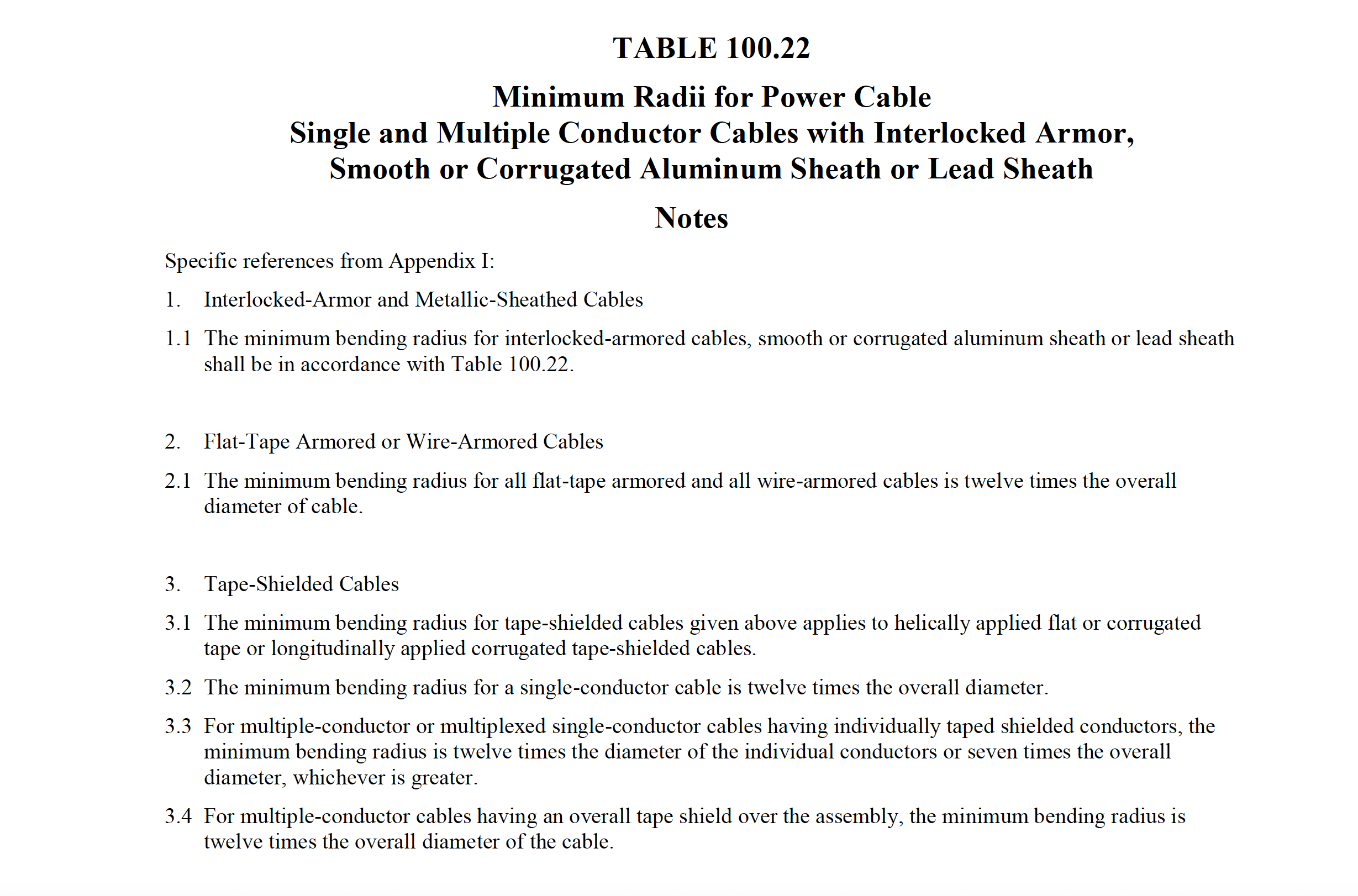
NETA
ATS / MTS
TABLE
100.22
|
|