Transformer Testing
Power transformers should undergo testing at various stages throughout their life cycle to ensure their performance, reliability, and safety.
Here are the key stages when power transformers should be tested:
Factory Testing
Power transformers are tested at the factory before they are
shipped to the customer. These tests verify the transformer's compliance with
design
specifications, performance characteristics, and quality standards.
Acceptance Testing (New Equipment)
Upon delivery and installation, before being put into service, power
transformers
should undergo acceptance testing. This ensures they're ready for operation and
helps spot any manufacturing defects or transportation-related issues.
Routine Maintenance Testing
Regular maintenance testing is performed at predetermined intervals, such as
3-5 years, to assess the condition of the transformer and identify any
developing issues.
Routine maintenance testing helps detect early signs
of degradation, insulation breakdown, or
other abnormalities that could impact the transformer's performance.
Periodic Diagnostic Testing
Periodic diagnostic testing delves deeper into the transformer's condition,
surpassing
routine maintenance. It encompasses detailed insulation testing, partial
discharge analysis,
sweep frequency response analysis (SFRA), and dissolved gas analysis (DGA).
These tests offer invaluable insights into the transformer's internal health,
aiding in the anticipation and prevention of potential failures or malfunctions.
After Repair or Overhaul
After any significant repair, refurbishment, or overhaul of a power
transformer, it is essential to conduct
post-repair testing. These tests ensure that the transformer has been
restored to its proper functioning and meets the required
performance standards.
| Transformer Testing, Low Voltage (< 600V) | |
|---|---|
|
NETA Test Procedure Categories 1. Dry Type Transformers
Rating:
Voltage Level:
Common Locations:
Example: : 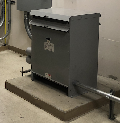
Test Procedures, Low Voltage (< 600V)Visual and Mechanical Inspection:
Visual and Mechanical Inspection list:
Visual and Mechanical Inspection list:
\( \Large PI= \huge \frac{10\; minutes}{1\; minutes} \)
Polarization Index Value < 1 Procedure:
Transformer Turns RatioThis is the ratio of the number of turns in the primary winding (N1) to the number of turns in the secondary winding (N2). The voltage times the amperage on the primary winding is equal to the voltage times the amperage on the secondary winding. \( \Large \text {turns ratio = } \) \( \Large \frac{N_{1}}{N_{2}} =\frac{V1}{V2}=\frac{I2}{I1} \)
Test DescriptionThe Transformer Turns Ratio (TTR) test is conducted to determine the turns ratio of a transformer. This test measures the number of turns in the primary winding compared to the secondary winding. The accepted values for the TTR test should not exceed a 0.5% deviation from the calculated values.
Test Result ValuesANSI/IEEE C57.12.00-2006, Section 9.1 The standard deviation between test results and calculated values should be within 0.5% of nameplate markings, with rated voltage applied to one winding. 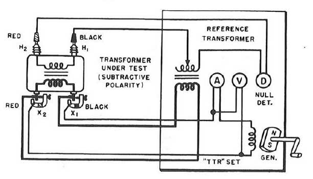
Insulation resistance (IR) test:The IR test is of value for future comparative purposes and also for determining the suitability of the transformer of energizing or application. The IR test must be successfully completed for factory warranty to be valid. The IR test must be conducted prior to energizing.
Description:
Purpose:
Polarization index (PI) test: \( \Large PI= \huge \frac{10\; min}{1\; min} \)
Polarization Index Value < 1 |
|
| Transformer Testing, High Voltage ( > 600V) | ||||||||||||||||||||||||||||||||||||||||||||||||||||||||||||||||||||||||||||||||||||||||||||||||||||||||||||||||||||||||||||||||
|---|---|---|---|---|---|---|---|---|---|---|---|---|---|---|---|---|---|---|---|---|---|---|---|---|---|---|---|---|---|---|---|---|---|---|---|---|---|---|---|---|---|---|---|---|---|---|---|---|---|---|---|---|---|---|---|---|---|---|---|---|---|---|---|---|---|---|---|---|---|---|---|---|---|---|---|---|---|---|---|---|---|---|---|---|---|---|---|---|---|---|---|---|---|---|---|---|---|---|---|---|---|---|---|---|---|---|---|---|---|---|---|---|---|---|---|---|---|---|---|---|---|---|---|---|---|---|---|---|
|
NETA Test Procedure Categories
1. Dry Type Transformers > 500 KVA
Voltage Level:
Common Locations:
Example: : 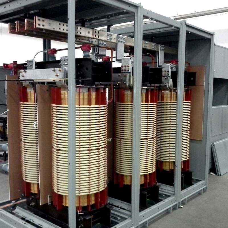
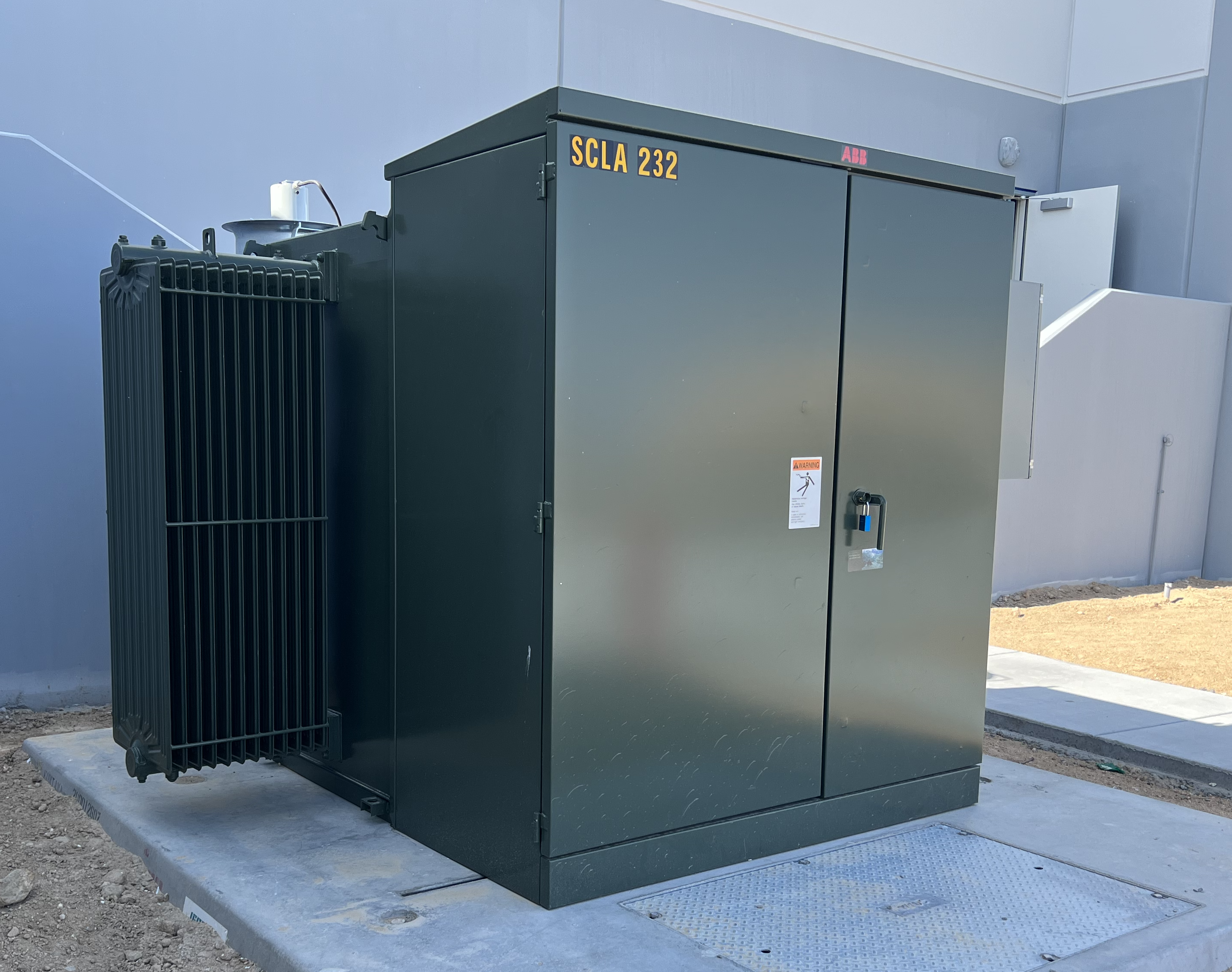
2. Liquid Filled Transformers
Voltage Level:
Common types:
Common Locations:
Example: : 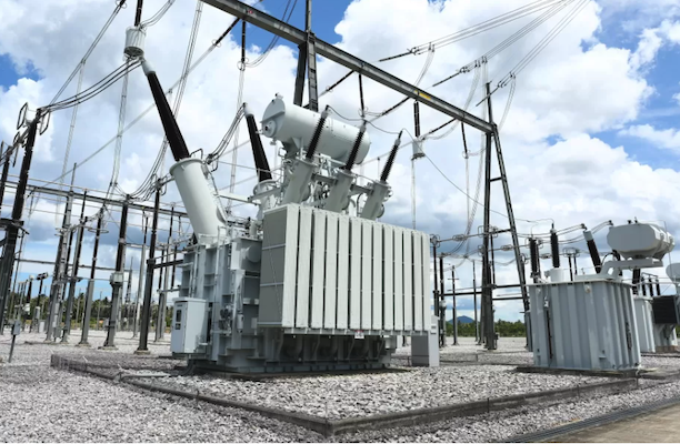
Test Procedures, High Voltage Voltage Voltage (>600V)New Equipment (Acceptance)Visual and Mechanical Inspection:
Visual and Mechanical Inspection:

Procedure:
Insulation Resistance Test:
Dry type and Oil filled Visual and Mechanical Inspection list:
\( \Large PI= \huge \frac{10\; minutes}{1\; minutes} \)
Polarization Index Value < 1 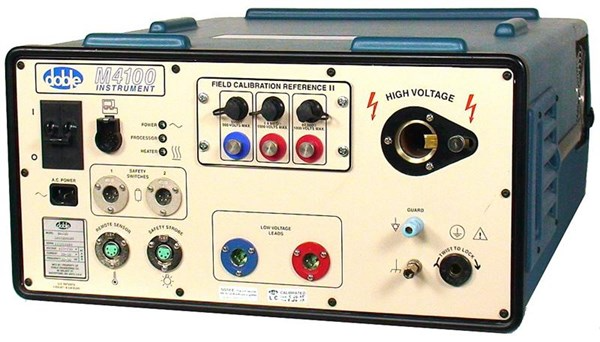
Doble M4000 Test Procedure
Transformer Turns RatioThis is the ratio of the number of turns in the primary winding (N1) to the number of turns in the secondary winding (N2). The voltage times the amperage on the primary winding is equal to the voltage times the amperage on the secondary winding. \( \Large \text {turns ratio = } \) \( \Large \frac{N_{1}}{N_{2}} =\frac{V1}{V2}=\frac{I2}{I1} \)
Test DescriptionThe Transformer Turns Ratio (TTR) test is conducted to determine the turns ratio of a transformer. This test measures the number of turns in the primary winding compared to the secondary winding. The accepted values for the TTR test should not exceed a 0.5% deviation from the calculated values.
Test Result ValuesANSI/IEEE C57.12.00-2006, Section 9.1 The standard deviation between test results and calculated values should be within 0.5% of nameplate markings, with rated voltage applied to one winding.
Insulation resistance (IR) test:The IR test is of value for future comparative purposes and also for determining the suitability of the transformer of energizing or application. The IR test must be successfully completed for factory warranty to be valid. The IR test must be conducted prior to energizing.
Description:
Purpose:
Polarization index (PI) test: \( \Large PI= \huge \frac{10\; min}{1\; min} \)
Polarization Index Value < 1 Winding ResistanceTransformer winding resistance testing is a common diagnostic test conducted on power transformers. It involves measuring the resistance of the transformer's windings to evaluate their condition and identify any potential issues. Here's an overview of transformer winding resistance testing: PurposeThe primary purpose of winding resistance testing is to assess the integrity of the transformer's windings and connections. By measuring the resistance, it helps detect abnormalities such as loose connections, high resistance joints, or damaged windings that could affect the transformer's performance. 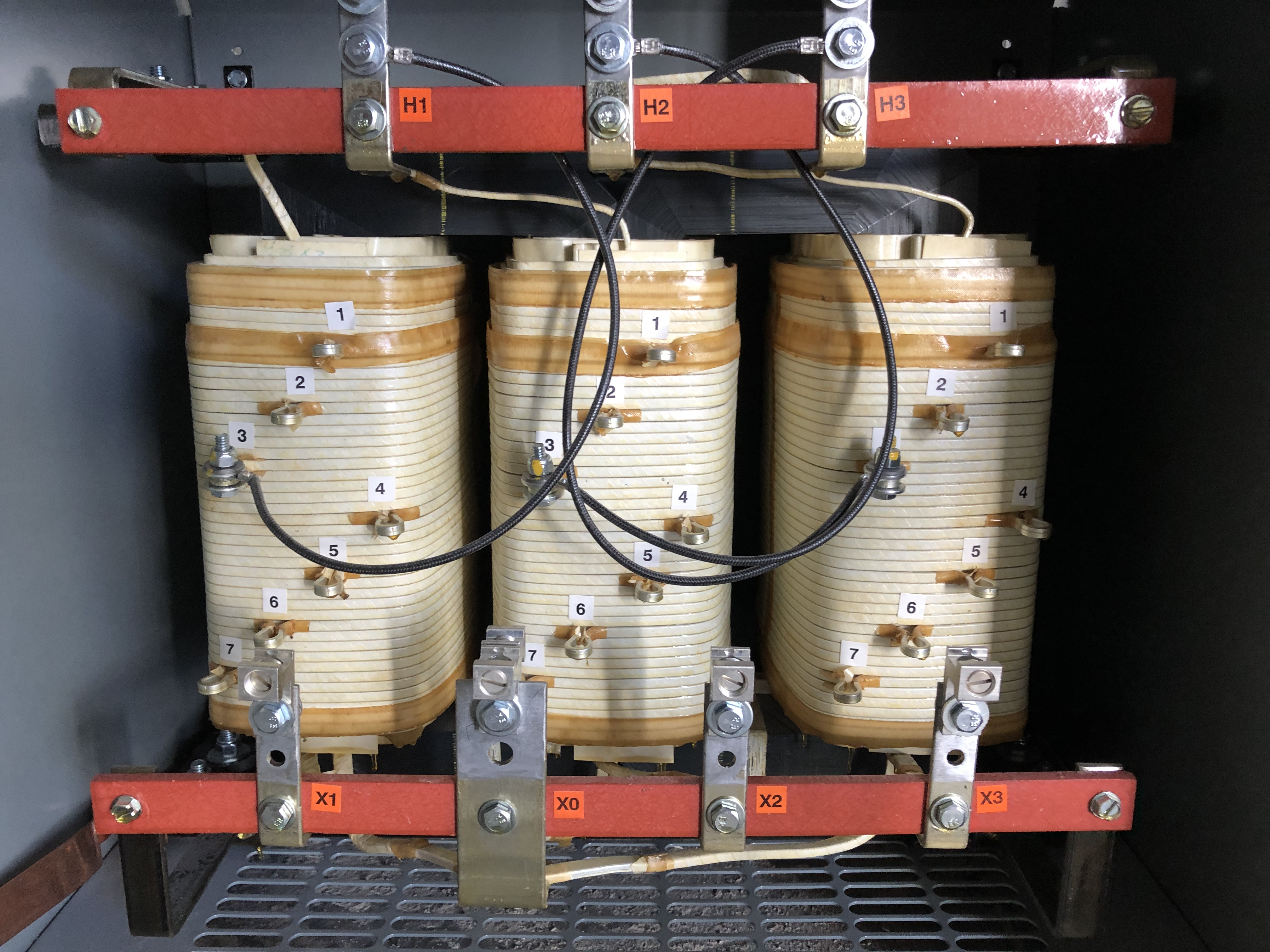
ProcedureTransformer winding resistance testing typically involves the following steps:
Interpretation of Results:The measured winding resistance values are compared to the expected or baseline values. Deviations from the expected values may indicate various issues:
Power Factor and Dissipation TestingPower Factor Testing and Dissipation Factor Testing are both methods used to assess the condition of insulating materials in electrical equipment, such as transformers, cables, and capacitors. These tests measure the dielectric losses within the insulation system to determine its health and detect potential issues such as moisture, contamination, or aging. Power Factor Testing and Dissipation Factor Testing are both methods used to assess the condition of insulating materials in electrical equipment, such as transformers, cables, and capacitors. These tests measure the dielectric losses within the insulation system to determine its health and detect potential issues such as moisture, contamination, or aging. Power FactorDefinitions: The power factor is the ratio of the real power (active power) dissipated in the insulation to the apparent power (total power) applied to the insulation. Purpose: Power factor testing is used to measure the insulation's dielectric losses at a specific frequency (usually the operating frequency, such as 60 Hz or 50 Hz). It helps in identifying the presence of moisture, contamination, and overall insulation condition. Dissipation Factor (DF) Testing:Purpose: Dissipation factor testing provides a more direct measure of the dielectric losses in the insulation material. It is particularly useful in identifying degradation in the insulating material itself, such as contamination, moisture ingress, or chemical breakdown. Definitions: The dissipation factor, also known as the loss tangent or tan δ, is the tangent of the phase angle between the resistive (real power) and reactive (stored energy) components of the current in the insulation. Transformer Inspection and Maintenance Checklist
Maintenance Transformer maintenance schedules should be determined according to the critical or noncritical nature of the transformer and the load that is connected to it. Proper maintenance includes regular inspections and repairs, maintaining and testing the transformer's liquid, and checking and testing the winding insulation. You should also follow any additional maintenance recommendations from the transformer's manufacturer. A guide for power transformer maintenance and testing, including how often you should do these tasks, is shown in the tables below. Routine inspection and repair involve visually checking the transformer's operating conditions and making any needed repairs. How often you do this depends on how critical the transformer is and the environment it's in. Transformer Inspection and Maintenance Checklist
|
||||||||||||||||||||||||||||||||||||||||||||||||||||||||||||||||||||||||||||||||||||||||||||||||||||||||||||||||||||||||||||||||
| Common Transformer Failures | |
|---|---|
OverviewTransformers are crucial components in the electrical power distribution and transmission networks, but they are prone to various types of failures due to their complex nature and operational stress. Understanding common transformer failures and the purpose and description of relevant diagnostic tests is essential for maintaining their reliability and extending their service life. Here are some common transformer failures and the corresponding tests used to diagnose and potentially prevent these issues: 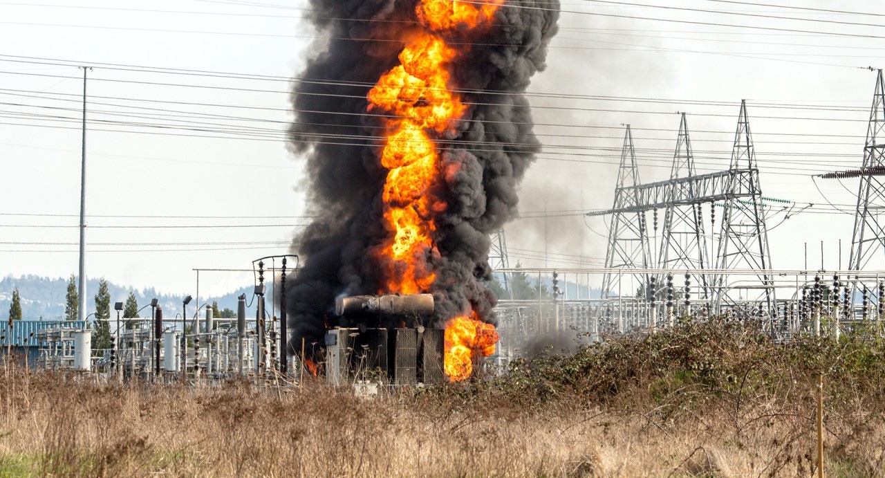
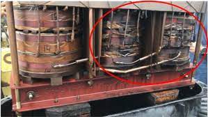
Mechanical Damage
Description: Mechanical factors can cause significant damage to transformer windings, potentially rupturing the solid insulation and leading to electrical failure. Damage to transformer windings may occur due to electromechanical forces or during shipping. Additional reasons for transformer failures include:
Liquid Leakage
Gas Leakage
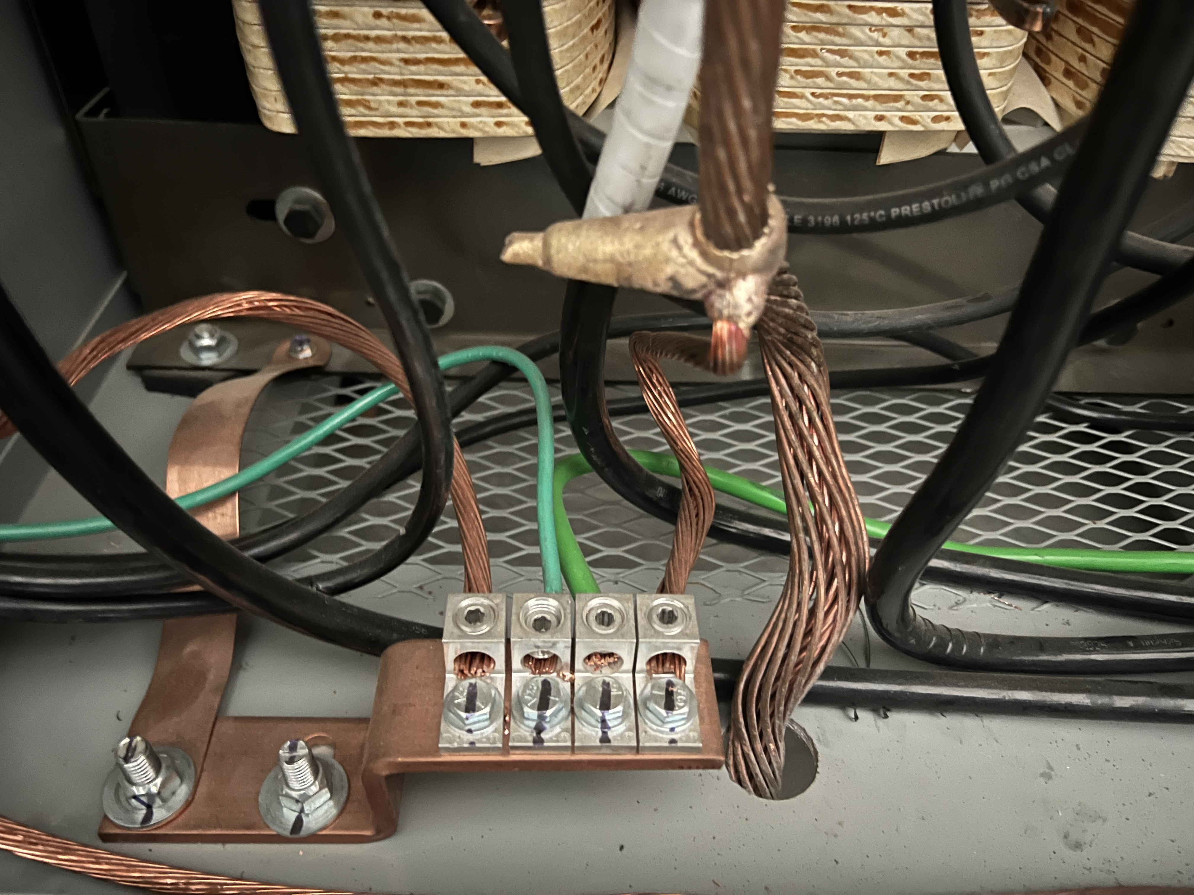
Broken Ground Connections
Diagnostic Tests:
Example: 
Insulation Breakdown
Description:
Solid Insulation: This type of solid insulation is particularly vulnerable to mechanical damage, which can occur from transformer movement or forces generated during short circuits. Additionally, faults in the insulation material might arise from the formation of copper sulfate (CuSO4) or from hot spots, which can develop due to insufficient oil levels or transformer overloading.
Diagnostic Tests:
Example: 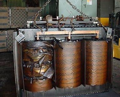
Winding Failures
Causes:
Diagnostic Tests:
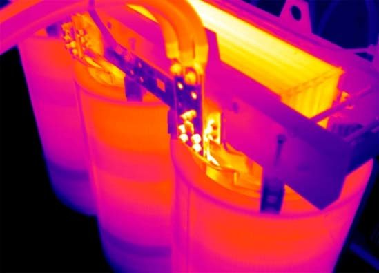
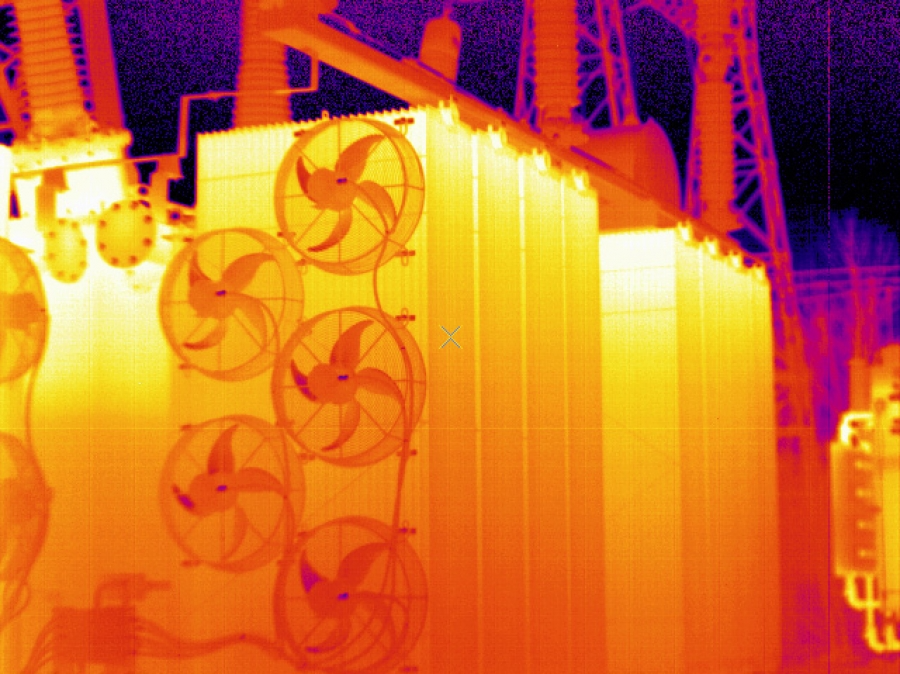
Overheating
Description:
Diagnostic Tests: Thermographic cameras used during routine maintenance can identified hot spots on the transformer casing, indicating potential overheating issues.
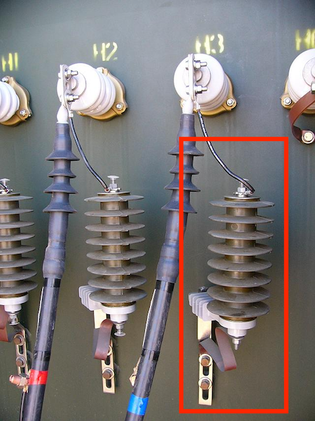
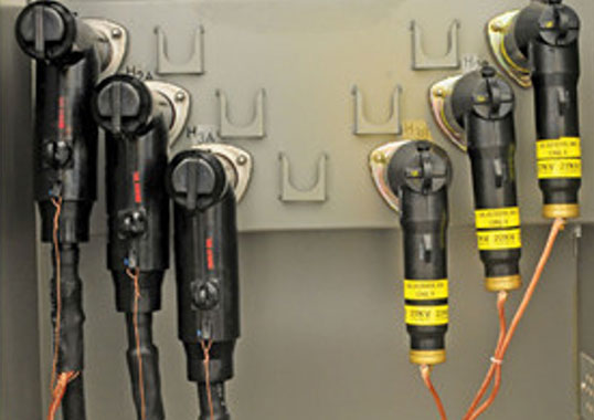
Bushing Failure
Causes:
Diagnostic Tests:
Example: 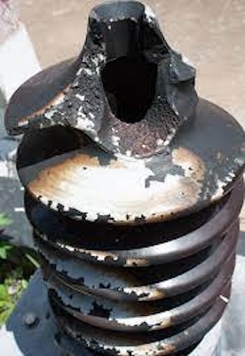
Core Faults
Causes:
Diagnostic Tests:
Example: 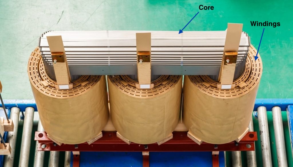
Oil Contamination
Description:
Transformer Oil: Cooling oil failures typically arise from two primary issues: malfunctioning oil circulation systems or inadequate heat transfer to the secondary cooling circuit. These problems can lead to increased oil viscosity and excessively high temperatures in the secondary cooling circuit. Additionally, the combination of moisture and oxygen with heat significantly contributes to oil contamination, which can produce conducting particles. As a result, the internal temperature of the transformer may rise, compromising the oil's insulating properties and potentially leading to a short circuit.
Diagnostic Tests:
Example: 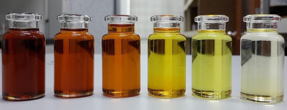
External Short Circuits
Description:
Diagnostic Tests:
Example:
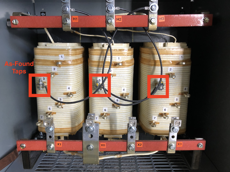
Tap Changer Failures
Causes:
Diagnostic Tests:
Example: 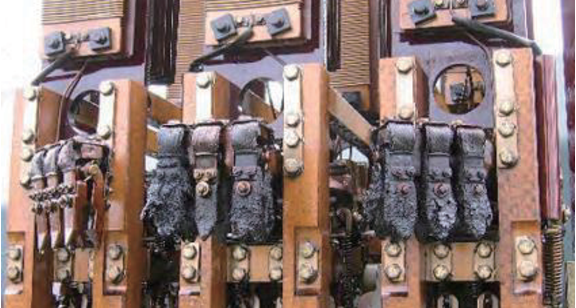
|
|
| Oil Sample Testing | |
|---|---|
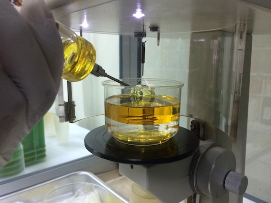
OverviewPurposeTransformer oil serves critical functions in power transformers, acting as both an insulating material and a cooling medium. Testing transformer oil is essential to ensure its effectiveness in these roles, as it helps evaluate physical and chemical properties that are crucial for the transformer's performance and safety. Regular testing can detect contaminants and chemical changes in the oil, which may indicate issues like insulation breakdown, overheating, or other operational faults within the transformer. Recommended Testing Schedule
Oil should be tested when the transformer is first installed to establish a baseline for future comparisons. Annually Standard practice for transformers under typical operating conditions. Bi-annually or Quarterly: Recommended if previous tests show deteriorating oil conditions or the transformer is in a harsh operating environment. Testing is crucial after incidents such as electrical faults or lightning strikes, as these can alter the oil's properties. For critical transformers or those with a history of issues, testing might be required more frequently, such as every 3 to 6 months, to monitor conditions closely. Acid Neutralization Number (ANN)PurposeThe primary purpose of the ANN test is to monitor the degradation of transformer oil over time. As the oil ages, it can become contaminated with oxidation products, which increase its acidity. This rise in acid content can lead to the corrosion of metal parts and degradation of the paper insulation within the transformer, potentially leading to operational failures. Therefore, the test helps in preventive maintenance planning by indicating when the oil needs to be treated or replaced to maintain the transformer's reliability and efficiency. DescriptionDuring the ANN test, a known quantity of transformer oil is titrated with a base (usually potassium hydroxide) to determine the amount of acid in the oil. The results are expressed in milligrams of KOH needed to neutralize the acids in one gram of oil, indicated as mg KOH/g. A higher Acid Neutralization Number suggests a greater presence of acidic compounds, indicating more severe oil degradation. Regular testing and monitoring allow for timely corrective actions, such as oil purification or replacement, to avoid costly repairs and downtime due to transformer damage. Industry StandardsASTM D974-Measures the acidity of petroleum products, including transformer oils, through color-indicator titration. ANSI/IEEE C57.106 -Provides guidelines for the acceptance and maintenance of insulating oil in electrical equipment, advising on testing and maintenance practices to ensure equipment integrity. IEC 62021-1-International standard specifically tailored for determining the acidity in insulating oils. Test Result Standards:New Oil: Should typically have an ANN of less than 0.1 mg KOH/g, indicating minimal acidity. In-Service Oil: An ANN value of up to 0.2 mg KOH/g is generally acceptable; values beyond this suggest potential oil degradation. Action Level: ANN values reaching or exceeding 0.5 mg KOH/g indicate significant degradation, necessitating immediate corrective actions such as oil treatment or replacement. Color TestPurposeThe main purpose of the Color Test is to assess the color of transformer oil as an indicator of its condition and suitability for continued use. This test is important because the color of transformer oil can change due to aging, oxidation, contamination, or the presence of by-products from thermal and electrical stresses. A darker color can indicate degradation or contamination, which may affect the oil's insulating and cooling properties. DescriptionThe Color Test is typically conducted by visually comparing the color of the oil sample to a standardized color chart or by using automated colorimeters that provide a precise measurement of color in terms of hue, saturation, and brightness. The test is simple: a sample of the transformer oil is placed in a clear container or special cuvette, and its color is then evaluated against standard color scales like the ASTM Color Scale. Industry StandardsASTM D1500- This standard describes the method for measuring the color of petroleum products by comparing them to a color scale under controlled lighting. The color is reported as a numerical value from 0.5 (very light) to 8.0 (very dark), providing a quantifiable measure of the oil's color. Test Result Standards:New Oil: New transformer oil typically has a very light color, usually around 0.5 to 1.0 on the ASTM color scale, indicating minimal impurities and good refining. In-Service Oil: As the oil is used within a transformer, it can darken due to aging, oxidation, and the effects of heat and electrical stresses. Oils with a color rating up to 2.0 are generally considered acceptable, but any noticeable change from the new oil should be investigated. Action Level: Transformer oils showing a color rating above 2.5 might indicate severe degradation or contamination, requiring further testing and potentially oil treatment or replacement. A dark color, especially nearing or exceeding 3.0, suggests urgent attention may be needed to prevent equipment damage or failure. Dielectric Breakdown VoltagePurposeThe main purpose of the Dielectric Breakdown Voltage test is to measure the ability of transformer oil to withstand electrical stress without failure. This test is crucial because transformer oil serves as both an insulator and a coolant. Over time, the oil can become contaminated with water, particles, and other impurities that significantly reduce its insulating properties. The Dielectric Breakdown Voltage test helps in assessing the quality and purity of the oil, thereby ensuring that it can effectively perform its insulating function. DescriptionThe Dielectric Breakdown Voltage test involves applying an AC voltage at a controlled rate to a sample of transformer oil between two electrodes. The voltage is increased until the oil fails electrically and allows current to pass through by arcing between the electrodes. The voltage at which this breakdown occurs is recorded as the dielectric breakdown voltage of the oil. The test is typically conducted under standard conditions to ensure consistency, with multiple tests performed on the same sample to establish a reliable breakdown voltage value. Industry StandardsASTM D877- A standard test method that uses a specific electrode configuration and test procedure to measure the dielectric breakdown voltage of insulating liquids. ASTM D1816- Provides a more sensitive measurement using a smaller electrode gap and is generally used for oils where higher levels of impurity are suspected. IEC 60156- An international standard that outlines procedures similar to ASTM but is widely adopted globally and may include specific variations tailored to regional testing practices. Test Result Standards:New Oil: Typically, new transformer oil should exhibit a dielectric breakdown voltage of at least 30 kV. This indicates good insulating properties suitable for effective transformer operation. In-Service Oil: The acceptable minimum values can vary, but generally, a dielectric breakdown voltage below 25 kV may suggest that the oil is no longer effective as an insulating medium and requires further treatment or replacement. Action Level: If the dielectric breakdown voltage falls below 20 kV, it is generally considered critical, and immediate actions such as oil filtration, degassing, or replacement are recommended to restore its insulating properties. Dissolved Gas Analysis (DGA)PurposeThe primary purpose of Dissolved Gas Analysis is to identify the presence and concentrations of specific gases dissolved in transformer oil that are produced by the decomposition of the oil and solid insulation under high temperature or electrical stress. By analyzing these gases, DGA can provide early warning signs of conditions such as overheating, arcing, and partial discharges within a transformer. This allows for preventative maintenance and can help avoid catastrophic failures and costly unplanned outages. DescriptionDuring DGA, a sample of transformer oil is extracted and analyzed using gas chromatography or similar methods to quantify the presence of key gases such as hydrogen (H2), methane (CH4), ethane (C2H6), ethylene (C2H4), acetylene (C2H2), carbon monoxide (CO), and carbon dioxide (CO2). Each of these gases can indicate different types of faults or degradation processes within the transformer. For example, hydrogen and methane can indicate low-energy discharges or early-stage overheating, while acetylene is a marker for high-energy arcing. Industry StandardsASTM D3612- This standard provides various methods for performing dissolved gas analysis in electrical insulating oils by gas chromatography. IEC 60567- An international standard that outlines the procedures for oil sampling and handling, gas extraction, and interpretation of dissolved gas analysis results in transformers. Test Result Standards:Normal Operation: Small amounts of gases such as nitrogen and oxygen are typically present due to the solubility of air in the oil. Low concentrations of fault gases can also be normal, depending on the transformer design and operating conditions. Fault Conditions: Specific gas ratios and concentrations can indicate different types of fault conditions:
Action Levels: DGA results are often interpreted using the Duval Triangle or other diagnostic tools that help classify the type of fault and its severity based on the ratios of the dissolved gases. Actions can range from continued monitoring (for minor anomalies) to immediate operational changes or shutdowns (for severe or critical gas levels). Interfacial TensionPurposeThe primary purpose of the IFT test is to evaluate the condition of transformer oil by detecting the presence of oxidation by-products and other polar contaminants. A high interfacial tension indicates that the oil is in good condition with minimal contamination, while a lower interfacial tension suggests that the oil contains more polar compounds and may be nearing the end of its useful life. DescriptionThe IFT test is performed by measuring the force required to break the interface between the transformer oil and a water layer under controlled conditions. This is usually done using a tensiometer, which measures the force in dynes per centimeter (dyn/cm). The test involves placing a drop of transformer oil on the surface of distilled water in a special apparatus and gradually increasing the surface area until the oil-water interface breaks. Industry StandardsASTM D971- This standard describes the method for measuring the interfacial tension of oil against water by the ring method. It is commonly used to determine the presence of polar compounds which are typically oxidative degradation products. IEC 62961- This international standard provides guidelines for the measurement of the interfacial tension of insulating oils, particularly focusing on the assessment of changes in interfacial tension as an indicator of oil degradation. Test Result Standards:New Oil: Typically, new transformer oil will have an interfacial tension of about 40 to 45 dynes/cm, indicating that the oil is relatively free of polar contaminants and suitable for use in electrical equipment. In-Service Oil: As the transformer oil ages, its interfacial tension usually decreases. An IFT value above 30 dynes/cm is generally considered acceptable for in-service transformer oils. Regular monitoring helps track the degradation over time. Action Level: If the IFT value falls below 25 dynes/cm, it suggests significant contamination and degradation. Oil with an IFT below 20 dynes/cm is generally considered unsuitable for continued use without treatment, and immediate action may be required to prevent damage to the transformer. Power Factor (Dissipation Factor)PurposeThe primary purpose of the Power Factor or Dissipation Factor test is to measure the dielectric losses in transformer oil, which indicate how much electrical energy is lost in the form of heat. This test provides insight into the condition of the oil, particularly its purity and degree of contamination by moisture, oxidation products, and other impurities that can affect its performance as an insulating medium. DescriptionThe test involves measuring the power factor (cos φ) or dissipation factor (tan δ) of the transformer oil at a specified temperature (usually 25°C or 100°C). These factors are measures of the dielectric loss angle in the insulating material and are calculated by applying an AC electric field to the oil in a test cell and measuring the resulting current. The power factor is the cosine of the phase angle between the applied voltage and the total current, while the dissipation factor is the tangent of this phase angle. Low values indicate good insulating properties, whereas higher values indicate greater contamination and reduced insulating effectiveness. Industry StandardsASTM D924- This standard describes the method for determining the dielectric constant and dissipation factor of electrical insulating liquids such as transformer oil. It provides detailed procedures for test cell setup, temperature control, and accurate measurement of these electrical properties. IEC 60247- This international standard outlines methods for measuring the relative permittivity, dielectric dissipation factor, and DC resistivity of insulating liquids. It covers a range of test conditions and provides guidance on interpreting test results. Test Result Standards:New Oil: Typically, new transformer oil should have a power factor or dissipation factor of less than 0.5% at 25°C, indicating high insulating quality and minimal conductive or polar contaminants. In-Service Oil: For in-service transformer oil, the power factor/dissipation factor should generally remain below 1.0% at 25°C. Values within this range suggest that the oil still maintains good insulating properties. Action Level: If the power factor/dissipation factor exceeds 1.0% at 25°C, it may indicate significant contamination or degradation of the oil, necessitating further investigation, oil treatment, or replacement. Values significantly higher than this threshold can impair the transformer's performance and increase the risk of failure. Specific GravityPurposeThe primary purpose of the Specific Gravity test is to determine the density of transformer oil, which affects how the oil behaves under temperature changes and its ability to effectively cool and insulate the transformer. Specific gravity also helps in identifying potential contamination with foreign substances that could alter the oil’s density and insulating properties. DescriptionThe Specific Gravity test measures the ratio of the density of transformer oil to the density of water at a specified temperature (usually 15°C or 25°C). This is done using a hydrometer, pycnometer, or density meter. The oil sample is placed in a test container, and its density is measured and compared to that of water. The result is a dimensionless number that indicates whether the oil is heavier or lighter than water. Industry StandardsASTM D1298- This standard outlines the method for determining the density, relative density (specific gravity), or API gravity of crude petroleum, petroleum products, or mixtures of petroleum and non-petroleum products. Test Result Standards:New Oil: Typically, the specific gravity of new transformer oil ranges from about 0.875 to 0.895 at 15°C. These values indicate that the oil is lighter than water and has the appropriate physical properties for use in transformers. In-Service Oil: The specific gravity of in-service transformer oil should not deviate significantly from the initial values. Stable specific gravity readings indicate that the oil maintains its original properties and effectiveness as a cooling and insulating medium. Action Level: Significant changes in specific gravity may indicate contamination (e.g., water ingress, which increases specific gravity) or degradation (e.g., by-products from oxidation, which might alter density). If specific gravity deviates markedly from normal ranges, further investigation or oil treatment may be required to restore its properties or prevent equipment damage. MoisturePurposeThe primary purpose of the Moisture Content test is to measure the water content in transformer oil to ensure it remains within safe limits. Water in transformer oil reduces its dielectric strength, promotes the formation of acids, and accelerates the aging of both the oil and the paper insulation. Monitoring moisture levels helps in maintaining the effectiveness of the oil as an insulating medium and in preventing transformer failures. DescriptionThe Moisture Content test, also known as the Karl Fischer titration, is a quantitative chemical analysis method used to determine the exact amount of water in transformer oil. The test involves mixing a sample of the oil with a reagent that reacts specifically with water. The amount of reagent consumed is measured and directly correlates to the amount of water in the sample. The results are typically expressed in parts per million (ppm). Industry StandardsASTM D1533- This standard describes the test method for determining water in insulating liquids by Coulometric Karl Fischer titration. It is highly precise and suitable for measuring even low levels of moisture in transformer oil. IEC 60814- This international standard outlines the method for determining water content in insulating liquids by automatic coulometric Karl Fischer titration. It is widely used for routine moisture content testing in transformer oils. Test Result Standards:New Oil: Typically, new transformer oil should contain less than 35 ppm of water to ensure optimal insulating properties and prevent any immediate risk to the transformer’s operation. In-Service Oil: For in-service transformer oil, moisture content should ideally remain under 50 ppm. Consistent monitoring helps in detecting any rise in moisture levels that could signify leaks, condensation, or other issues affecting the transformer. Action Level: Moisture levels exceeding 50 ppm in transformer oil are generally considered actionable, and levels above 100 ppm are deemed critical, requiring immediate attention. At these levels, the risk of insulation failure increases significantly, and measures such as oil dehydration or replacement might be necessary to restore the oil’s performance and protect the transformer. |
|
| NETA Test Procedure | |
|---|---|
NETA ATS-20177.2.1.1 Transformers, Dry Type, Air-Cooled, Low-Voltage, SmallNOTE: This category consists of
power transformers with windings
rated 600 volts or less and sizes equal to
or
|
|
| NETA Test Procedure | |
|---|---|
NETA ATS-20177.10.1 Instrument Transformers, Current TransformersA. Visual and Mechanical Inspection:
B. Electrical Tests:
C. Test Values – Visual and Mechanical
D. Test Values – Electrical
NETA ATS-20177.10.2 Instrument Transformers, Voltage TransformersA. Visual and Mechanical Inspection:
B. Electrical Tests:
C. Test Values – Visual and Mechanical
D. Test Values – Electrical
NETA ATS-20177.10.3 Instrument Transformers, Coupling-Capacitor Voltage TransformersA. Visual and Mechanical Inspection:
B. Electrical Tests:
C. Test Values – Visual and Mechanical
D. Test Values – Electrical
NETA MTS-20197.10.1 Instrument Transformers, Current TransformersA. Visual and Mechanical Inspection:
B. Electrical Tests:
C. Test Values – Visual and Mechanical
D. Test Values – Electrical
NETA MTS-20197.10.2 Instrument Transformers, Voltage TransformersA. Visual and Mechanical Inspection:
B. Electrical Tests:
C. Test Values – Visual and Mechanical
D. Test Values – Electrical
NETA MTS-20197.10.3 Instrument Transformers, Coupling-Capacitor Voltage TransformersA. Visual and Mechanical Inspection:
B. Electrical Tests:
C. Test Values – Visual and Mechanical
D. Test Values – Electrical
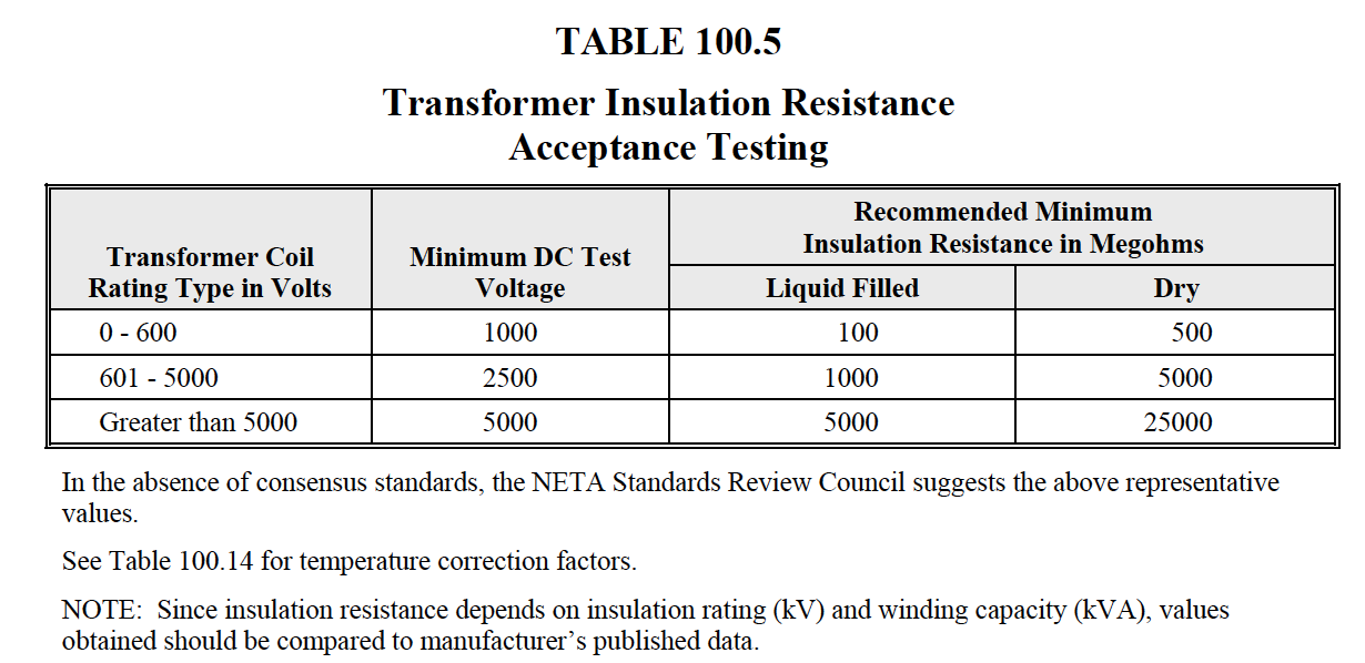
NETA
ATS / MTS
TABLE
100.5

NETA
ATS / MTS
|
|