What is Arc Flash ?
Industrial and commercial electrical systems inherently carry the risk of arc flash hazards. An arc flash is a dangerous electrical event characterized by an intense release of heat, light, and energy. It occurs when an electrical arc forms between two conductive materials or due to a system fault, often caused by equipment failure, inadequate maintenance, or human error.
To help facilities meet their safety compliance requirements, GPS offers turnkey services. We assist in evaluating and developing comprehensive workplace safety programs, including detailed arc flash engineering studies of electrical systems.
The following sections of this page provide detailed information on the steps involved in developing an arc flash report. Additionally, you will find technical information on key topics related to arc flash analysis, report development, mitigation strategies, and safety compliance.
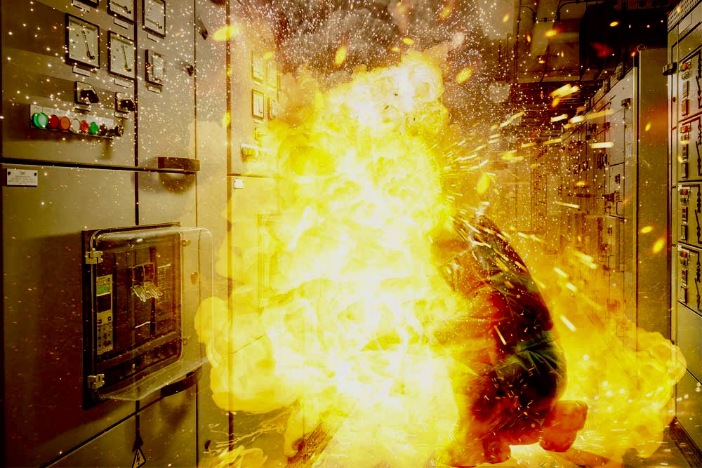
During an arc flash, temperatures can reach extremely high levels, often exceeding 35,000 degrees Fahrenheit (19,400 degrees Celsius) . The release of this thermal energy can cause severe burns, ignite flammable materials, and result in explosions, leading to serious injuries or fatalities. The intense light emitted during an arc flash can also cause temporary or permanent vision impairment.
| Arc Flash Videos | |
|---|---|
|
|
|
Does OSHA require I perform a study
OSHA requires employers to protect employees from electrical hazards, including arc flash.
29 CFR 1910.269, section III Protection Against Heat Energy
"Calculation methods. Paragraph (l)(8)(ii) of § 1910.269 provides that, for each employee exposed to an electric-arc hazard, the employer must make a reasonable estimate of the heat energy to which the employee would be exposed if an arc occurs. Table 2 lists various methods of calculating values of available heat energy from an electric circuit..."
Table 2
- Standard for Electrical Safety Requirements for Employee Workplaces, NFPA 70E-2012, Annex D, "Sample Calculation of Flash Protection Boundary."
- Doughty, T.E., Neal, T.E., and Floyd II, H.L., "Predicting Incident Energy to Better Manage the Electric Arc Hazard on 600 V Power Distribution Systems," Record of Conference Papers IEEE IAS 45th Annual Petroleum and Chemical Industry Conference, September 28-30, 1998.
- Doughty, T.E., Neal, T.E., and Floyd II, H.L., "Predicting Incident Energy to Better Manage the Electric Arc Hazard on 600 V Power Distribution Systems," Record of Conference Papers IEEE IAS 45th Annual Petroleum and Chemical Industry Conference, September 28-30, 1998.
- Guide for Performing Arc-Flash Hazard Calculations, IEEE Std 1584-2002, 1584a-2004 (Amendment 1 to IEEE Std 1584-2002), and 1584b-2011 (Amendment 2: Changes to Clause 4 of IEEE Std 1584-2002).
- ARCPRO, a commercially available software program developed by Kinectrics, Toronto, ON, CA.
Is NFPA 70E a voluntary standard and not something that OSHA enforces?
This question was addressed in a letter by OSHA. OSHA's response constitutes an interpretation of the discussed requirements.
OSHA response letter dated November 4, 2004
Response: OSHA approaches NFPA 70E from both a standards perspective and an enforcement perspective. From a standards perspective, OSHA views NFPA 70E as the primary consensus standard addressing electrical hazards associated with electrical utilization systems...
...From an enforcement perspective, OSHA does not enforce NFPA 70E. OSHA enforces its own standards that relate to electrical hazards. OSHA may, however, use NFPA 70E to support citations for violations relating to certain OSHA standards, such as the general requirements for personal protective equipment found in 29 CFR 1910.335. An example of this would be consulting NFPA 70E’s Flash Hazard Boundary when considering citations for personal protective equipment under 1910.335.
Steps for Developing an Arc Flash Report
Creating an arc flash hazard analysis report is a critical step in ensuring electrical safety in power distribution systems. This analysis helps in identifying the potential exposure to arc flash energy that could result in severe injury or death. The following steps outline how to perform a comprehensive arc flash hazard analysis, incorporating Short Circuit Analysis, Protective Device Coordination, and Arc Flash Analysis itself.
Data Collection of Existing Facilities
The initial step involves gathering all necessary system data which includes:
- Electrical one-line diagrams
- Details of all equipment including transformers, circuit breakers, fuses, conductors, and protective relays
- System modes of operation
- Specifications and settings of all protective devices
- Load data and historical operation data if available
When modeling a new construction project, single-line diagrams and manufacturer's gear submittals will usually have all the necessary information needed to model the new system
Order Utility Fault Report
After collecting the initial data, order a fault report from the utility provider. This report provides critical information about the available fault current supplied by the utility, which is essential for accurate short circuit analysis:
- Contact the utility to request the maximum available fault currents at the point of common coupling.
- Ensure the utility data includes different operational conditions that might affect the fault current levels.
System Modeling
Using the collected data, model the electrical system using appropriate engineering software designed for electrical analysis (such as ETAP, SKM Systems Analysis Power Tools, or EasyPower). This model should accurately reflect the physical and operational characteristics of the power system.
Short Circuit Analysis
Perform a short circuit analysis to determine the maximum available fault currents at various points in the system. This analysis is crucial as it provides the base data required for subsequent protective device coordination and arc flash analysis:
- Calculate the three-phase, line-to-line, and line-to-ground fault currents.
- Assess the interrupting ratings of protective devices against calculated fault currents to ensure all equipment is adequately rated.
Protective Device Coordination
This step involves setting and coordinating the timing of protective devices to minimize the interruption of electrical service and enhance safety by reducing fault damage:
- Adjust the timing and settings of circuit breakers and relays to achieve optimal coordination.
- Use time-current curves to ensure that devices operate sequentially from the point of fault, starting from the closest device upstream.
Arc Flash Analysis
Conduct an arc flash analysis to estimate the incident energy levels and the arc flash boundary at various points in the system:
- Utilize the IEEE 1584 guide for calculating arc-flash hazard incident energy.
- Input the gathered fault current and protective device coordination data into the arc flash calculation formulas.
- Determine the incident energy levels, arc flash boundaries, and necessary personal protective equipment (PPE) classifications.
Reporting
Compile a comprehensive arc flash hazard analysis report that includes:
- An executive summary of findings and recommendations.
- Detailed descriptions and results of the short circuit analysis, protective device coordination, and arc flash analysis.
- Recommendations for equipment upgrades, changes in protective device settings, or operational changes to reduce arc flash hazards.
- Updated electrical one-line diagrams reflecting the current system configuration.
Labeling
Based on the results from the arc flash analysis, create and affix labels on all electrical equipment that clearly display the arc flash boundary, incident energy at the working distance, and required PPE.
Arc Flash Hazard Report Standards:
Arc flash analysis reports are performed using the following standards:
National Electrical Code (NEC), NFPA 70 contains requirements for warning labels.
NFPA 70E: Standard for Electrical Safety in the Workplace provides guidance on implementing appropriate work practices that are required to safeguard workers from injury while working on or near exposed electrical conductors or circuit parts that are or will become energized.
Institute of Electrical and Electronics Engineers (IEEE) 1584 publishes the guide for Performing Arc Flash Hazard Calculations provides a method of calculating the incident energy to define the safe working distance and aid in selection of overcurrent protective devices and PPE.
| Short Circuit Analysis Report | ||||||||||||||||||||||||||||||||||||||||||||||||||||||||
|---|---|---|---|---|---|---|---|---|---|---|---|---|---|---|---|---|---|---|---|---|---|---|---|---|---|---|---|---|---|---|---|---|---|---|---|---|---|---|---|---|---|---|---|---|---|---|---|---|---|---|---|---|---|---|---|---|
Short Circuit AnalysisShort circuit analysis, also known as fault current analysis, involves studying and calculating the electrical currents that flow when an abnormal condition, such as a short circuit or fault, occurs in an electrical power system. A short circuit is a low-resistance connection between two energized devices, such as conductors, resulting in a high current flow.
Modeling
Calculating Fault Currents
Equipment Evaluation
Protective Device Coordination: 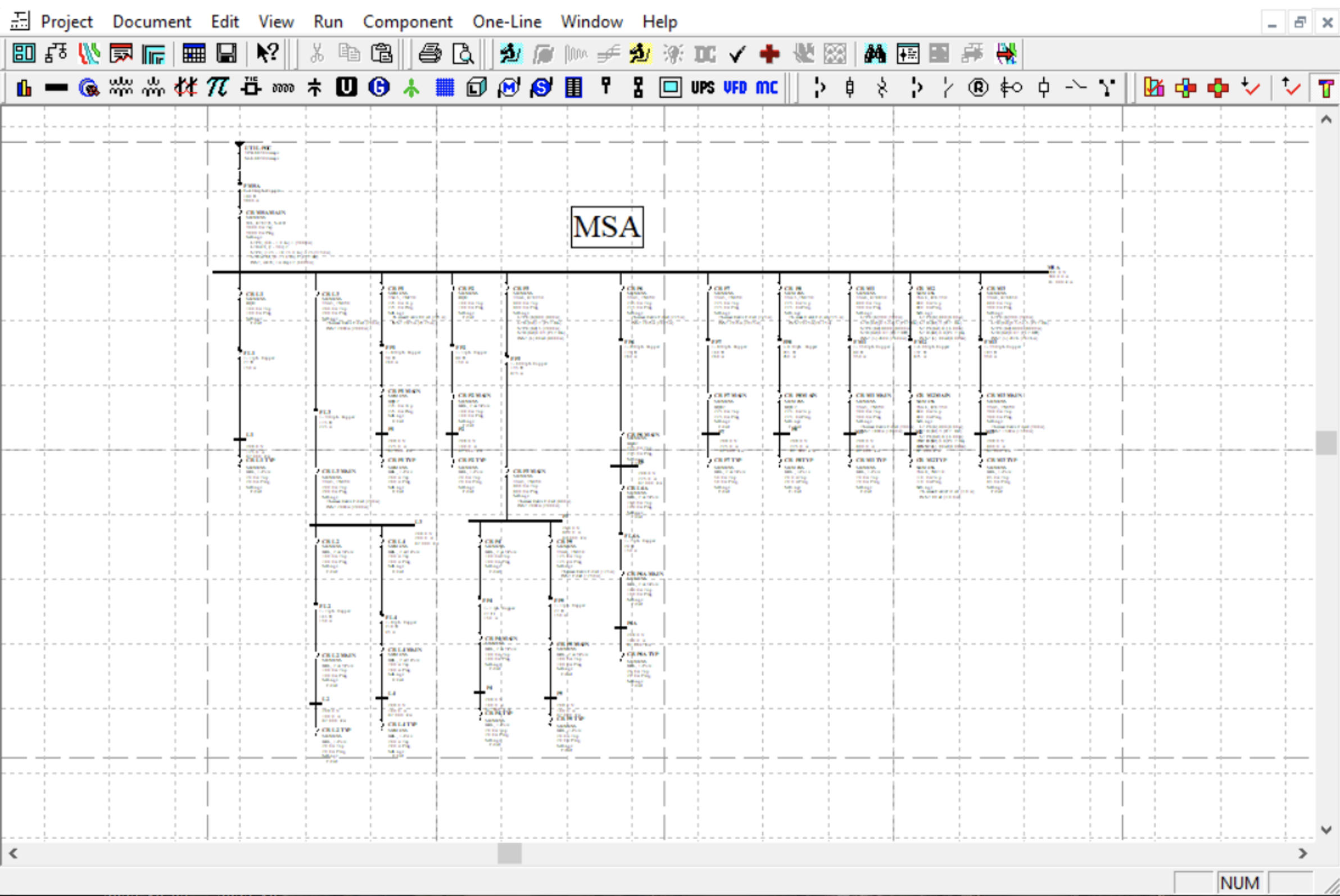
Naming ConventionThe single-line diagram in the report serves as a graphical representation of the current computer model used for the analysis. Each component depicted on the single-line diagram is identified by a unique label corresponding to the type of equipment and the equipment served by that particular device. For instance, a component labeled as "CB T1" denotes a circuit breaker (CB) serving T1. The report employs common identifiers, and the following are examples of such identifiers used throughout.
Fault Current CalculationsShort circuit analysis of the system model is done using SKM's A_FAULT module, which determines the maximum fault levels at each bus; typically, this would be inside switchgear and panels. The module automatically compare these values against manufacturer short circuit current ratings. A_FAULT ModuleThe module provides calculated fault values, complies with ANSI/IEEE C37 standard for fault currents calculations. The software also uses the standard's evaluation factors and ratios required for high- and low-voltage device short circuit duty evaluation. A_FAULT generates three types of short-circuit reports for both balanced (three-phase bolted) and unbalanced (line-to-ground) faults. A complete list of all these values is provided in the output report At each bus, or enclosure, the minimum withstand and interrupting rating required for the enclosure and protective devices inside of it is reported in the equipment evaluation report. 
Short Circuit AnalysisUpon creating the model, a comprehensive assessment of the system is being conducted to identify the peak fault levels impacting the equipment encompassed in the project's scope. The analysis employs the SKM AFault method, leveraging the ANSI/IEEE C37.13 standard to compute fault currents. Notably, this method diverges from traditional short circuit calculations by addressing the asymmetrical nature of initial fault currents, incorporating a DC offset, as depicted in the accompanying figure. This asymmetry in the initial current can persist across multiple cycles and is observed through the short time and instantaneous trip components in circuit breakers. 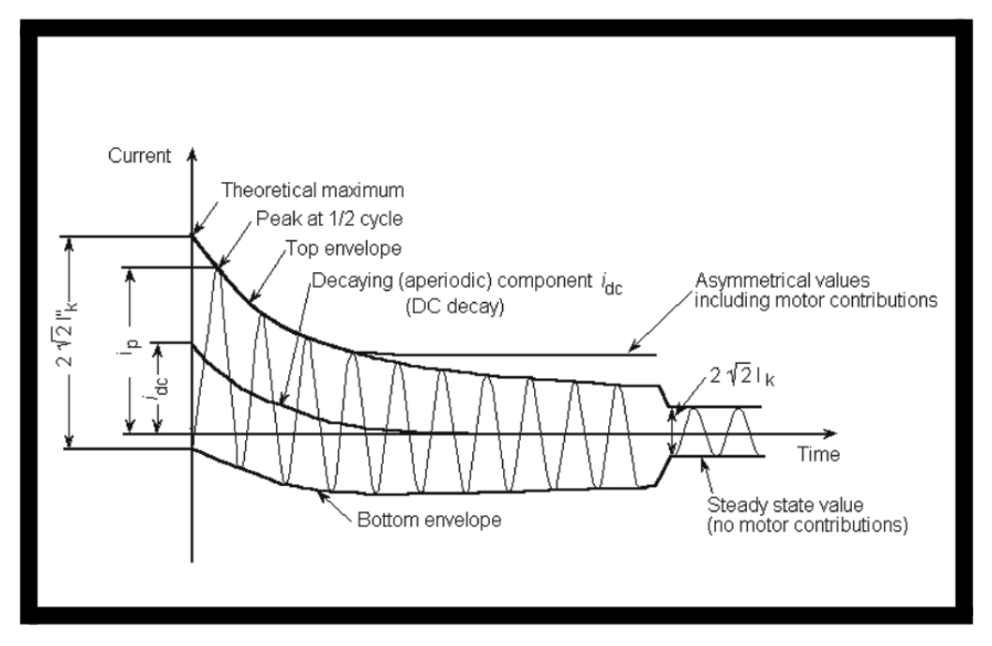
Test Power Factor and Asymmetry FactorThe SKM AFault analysis calculates crest current values and determines the required interrupting ratings for the proper selection of power circuit breakers, insulated and molded case breakers, and fuses. Crest current is utilized to evaluate the interrupting rating of low voltage breakers. These values are based on the ANSI (NEMA) specified test power factor for these breakers, as shown below:
The Asymmetrical duty can be calculated as follows:This value should not exceed the equipment rating times the appropriate test factor for the device. For devices where the calculated X/R ratio is greater than the test X/R ratio listed above, a symmetrical multiplying factor must be evaluated as well. First half cycle of asymmetrical fault current:
\( \Large I_{asym \frac{1}{2}cycle}=I_{rms-sym} \times \sqrt{1+2e^{\frac{-2\pi}{\frac{X}{R}}}} \)
This value should not exceed the equipment rating times the appropriate test factor for the device. If the calculated X/R ratio exceeds the test X/R ratio, an additional symmetrical factor needs evaluation. The symmetrical rating is calculated as follows:
\( \Large I_{sym-LVF}= I_{rms-sym} \times \frac{\sqrt{1+2e^{\frac{-2\pi}{\frac{X}R^{system}}}} }{\sqrt{1+2e^{\frac{-2\pi}{\frac{X}{R^{test}}}}} } \)
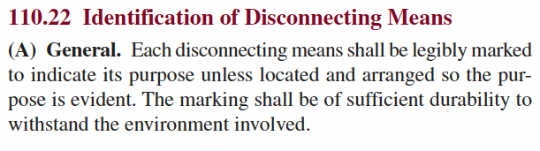
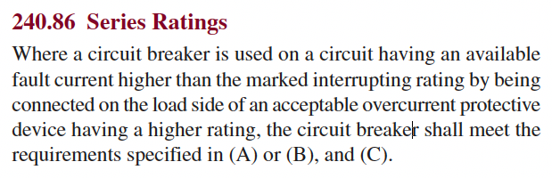
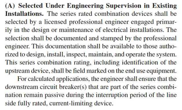
Equipment Evaluation CriteriaWhen evaluating the interrupting capability of low voltage protective devices two ratings can be used, self-protected or series combination. Self-protected ratings (fully rated) are the labeled ratings from the manufacturer for the equipment. If the fault currents seen by the protective devices exceed the self protected ratings, it may result in failure during operation. Equipment failure is explosive in nature, can cause injury or death to personnel, and will severely damage equipment resulting in a prolonged equipment outage. Series combination ratings (Series rating) is an alternative to self-protected ratings. Where fault levels exceed the rating of a device, one or more devices upstream operate simultaneously and limit the current to a level below the self-protected rating of the device. The series rating applied is only valid for tested combinations of devices. Peak let-through of current-limiting devices is not acceptable for use with molded case circuit breakers since their operation creates a dynamic impedance that can limit the current seen by upstream devices below their current limiting range. When series ratings are used, the National Electrical Code (NEC), Section 110-22, requires that equipment be field marked to indicate the equipment has been applied with a series combination rating. This marking must be legible to personnel who work on the equipment. Series combination ratings (Series rating) is an alternative to self-protected ratings. Where fault levels exceed the rating of a device, one or more devices upstream operate simultaneously and limit the current to a level below the self-protected rating of the device. The series rating applied is only valid for tested combinations of devices. Peak let-through of current-limiting devices is not acceptable for use with molded case circuit breakers since their operation creates a dynamic impedance that can limit the current seen by upstream devices below their current limiting range. When series ratings are used, the National Electrical Code (NEC), Section 110-22, requires that equipment be field marked to indicate the equipment has been applied with a series combination rating. This marking must be legible to personnel who work on the equipment. Medium Voltage EquipmentMedium voltage equipment evaluation has two components: momentary and interrupting ratings. The momentary rating is the asymmetrical current seen ½ cycle after the fault occurs. The interrupting rating reflects the fault duties at the time when a protective device will operate to clear a fault (typically 2, 3, 5 or 8 cycles). ANSI allows a simplified momentary rating calculation of 1.6 times the symmetrical fault duty. The actual value is calculated as follows.
\( \Large I_{asym \frac{1}{2}cycle}= I_{rms-sym} \times \sqrt{1+2e^{\frac{-2\pi} {\frac{X} {R}} \times C} } \)
\({C}\)\(\text{= is the first} \frac{1}{2}cycle\) utility InformationWhen performing a short circuit analysis for the purpose of should always be based on actual fault current information provided by a utility company. Infinite Bus method is a simplified method for approximating the maximum short circuit current at the load-side of a transformer feeding a distribution system. While this method The infinite bus calculation method is generally NOT suitable for use with Arc Flash Studies since a lower short circuit current could result in the overcurrent protective device taking longer to operate resulting in a greater incident energy exposure. Full load Amps (3 phase)\( \Large FLA_{pri} = \huge \frac{VA}{ \sqrt{3} \times V_{L1} } \) Full load Amps (Single Phase)\( \Large FLA_{pri} = \huge \frac{VA}{ V_{L1} } \)
\( \Large VA\) : is the apparent power rating of the transformer in VA or kVA. Equipment Rating EvaluationThe purpose of the equipment evaluation is to compare the maximum calculated short-circuit currents to the short-circuit ratings of protective devices or the withstand rating of an enclosure. The Device Evaluation Report, located in the appendix of the project report, provides a summary of fault duties. It compares these duties, factoring in ANSI multipliers, with equipment ratings for each location within the modeled system. This comparison aims to determine whether the device is capable of either interrupting or withstanding the fault currents present in the electrical system where it's applied. 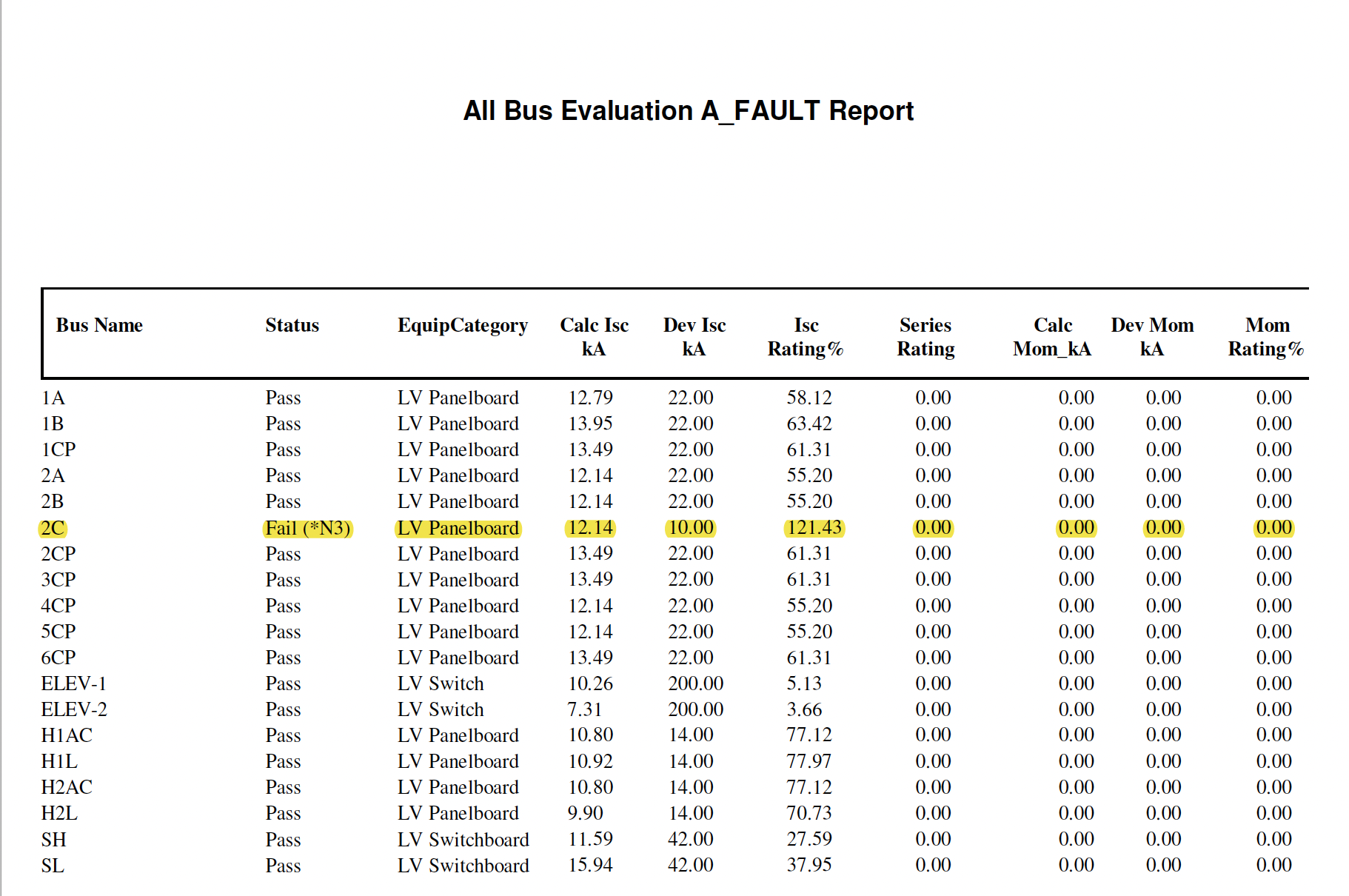
Bus Name
Status
Equipment Category
Calc Isc_kA
Dev Isc_kA
Isc Rating%
Series Rating
Calc Mom_kA
Dev Mom_kA
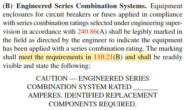
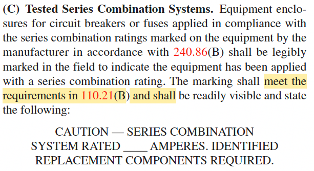
Mom Rating% Series RatingWhen assessing the ability of protective devices to interrupt available fault duties, two types of ratings come into play: Self-Protected and Series Rated. Self-Protected ratings refer to the manufacturer's nameplate interrupting ratings for both devices and equipment. If the actual fault duties exceed these specified ratings, operational failure can occur, leading to potential injury to personnel and damage to equipment. Series Ratings are assigned to tested combinations of devices, as required per NEC 240.86 (B) . In cases where fault levels surpass the rating of a single device, one or more devices upstream operate simultaneously, collaboratively sharing the task of interrupting energies. To comply with the National Electrical Code, specifically Section 110.22 (A)(B)(C), when applying circuit breakers or fuses in line with the series combination ratings marked on the equipment by the manufacturer, equipment enclosures must be legibly marked in the field. These markings serve as a clear indication that the equipment has been configured with a series combination rating, ensuring compliance with industry standards and promoting safe and reliable electrical systems.
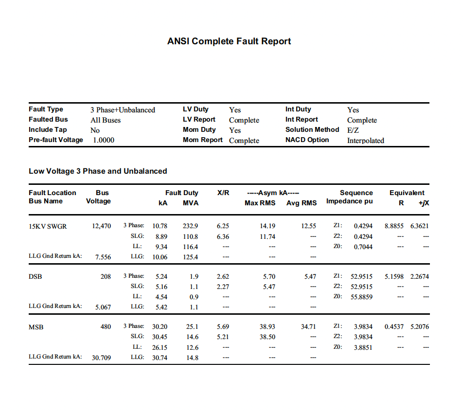
SIEMENS Input / Output ReportInput reports provide a detailed list of all the modeled equipment in the study Output reports provides a detailed list of Fault current values at each bus 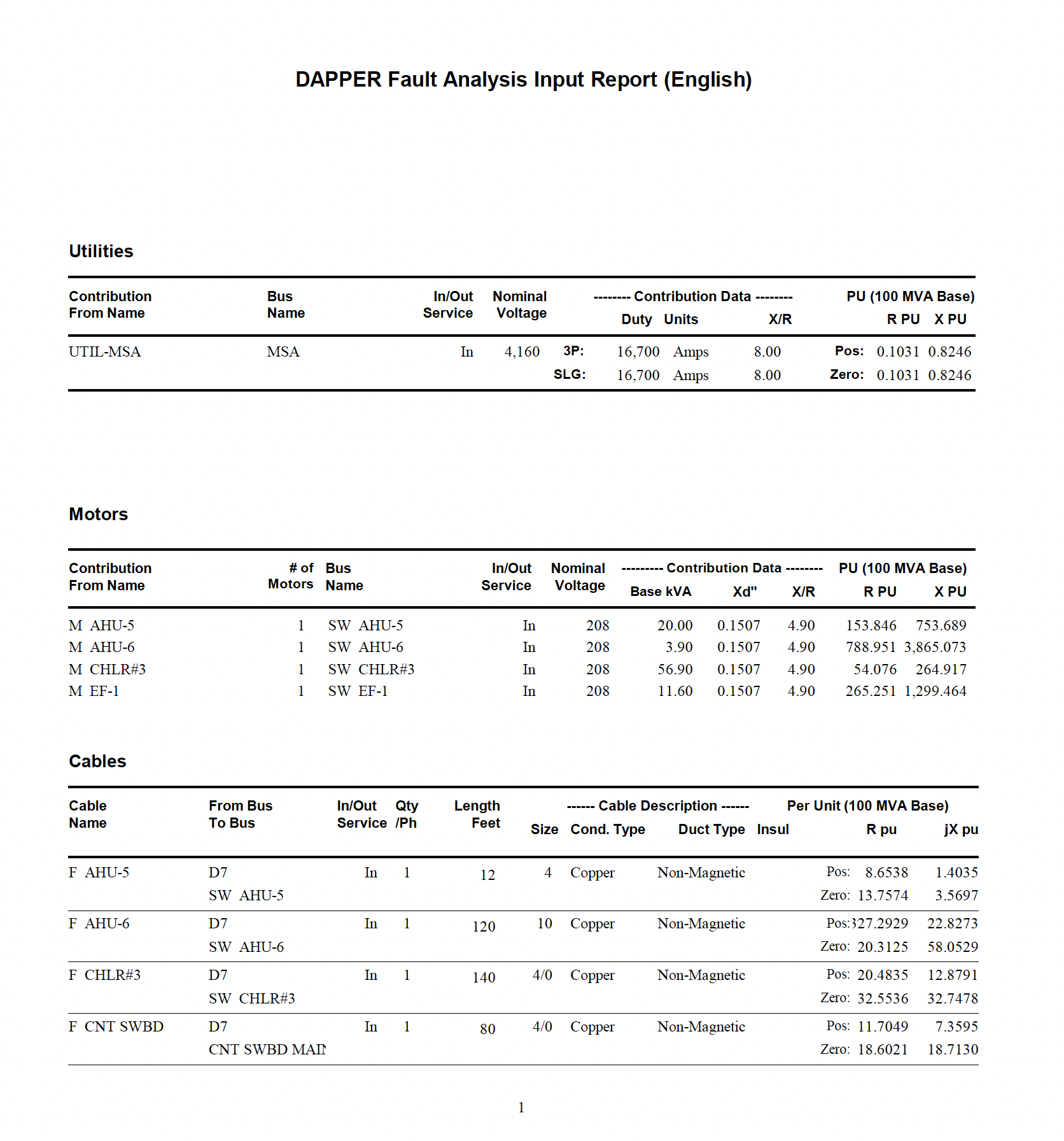
Glossary of Terms
Frequently Asked QuestionsQuestion 1:What is the Difference between Current Interrupting Rating (AIC) and Withstand Current Rating?Answer:The difference between a device's current interrupting rating (AIC) and its withstand current rating involves two critical aspects of electrical equipment performance under fault conditions: Current Interrupting Rating (AIC): This rating specifies the highest level of fault current that an electrical device such as a circuit breaker, fuse, or other protective device can safely interrupt without damage. It essentially tells you how much current the device can handle in the event of a short circuit or fault condition without failing to operate properly. This rating is crucial for ensuring that the protective device can effectively protect the circuit by interrupting excessive current flows and preventing equipment damage or fire hazards. Withstand Current Rating: This rating indicates the maximum level of current an electrical component can tolerate without sustaining physical or operational damage when a fault occurs, but it does not necessarily interrupt the current. It’s about enduring the fault long enough (typically for a few cycles of the current waveform) for the upstream protective device to clear the fault. This rating ensures that the device can survive the conditions of a fault long enough for protective measures to act without the integrity of the device being compromised. Application to Different Types of Equipment:Panelboards: If fully rated the short circuit rating of a panel is listed on the rating nameplate of the panel. This rating will be the withstand rating of the panel interior or the interrupting rating of the lowest rated overcurrent device in the panel. equal to short circuit interrupting rating of the If series rated, a sticker with field added interrupting rating should be visible on the panelboard without removing the dead front. The installer would have written the series rating on the sticker. If fully rated, the interrupting rating is equivalent to the lowest rating of any contained circuit breaker, whether main or branch. Typically located on the backside of the dead front cover, a sticker describes this process of determining the rating. UL and NEC do not require a label listing the specific interrupting rating for fully rated panelboards. Protective Devices (Circuit Breakers, Fuses): Primarily concerned with AIC since their main function is to interrupt fault currents safely. The ability to withstand the fault current until it is cleared is inherent in their AIC rating. Fused Switches: Require an AIC rating for the fuse itself, as it needs to interrupt fault currents. The switch apparatus typically needs a withstand rating, showing it can handle fault currents briefly until the fuse operates. Non-Fused Switches: These generally need a withstand current rating because they do not interrupt fault currents. Their role is to endure the fault condition until a protective device elsewhere clears the fault. |
||||||||||||||||||||||||||||||||||||||||||||||||||||||||
| System Protection & Device Coordination | |
|---|---|
|
System Protection
System protection in electrical power systems is crucial for maintaining safety and reliability. Protective devices detect and isolate faults, preventing damage to equipment and ensuring the system remains operational. Two key protective elements are overcurrent protection (50/51) and instantaneous protection (50). Understanding how these elements work and are coordinated is essential for effective system protection. Overcurrent Protection (51)Overcurrent protection is designed to handle situations where the current flowing through a circuit exceeds a safe level. This could happen due to overloads or short circuits. The overcurrent protection element operates based on two main factors: the magnitude of the current and the duration of the overcurrent. Instantaneous Protection (50)Instantaneous protection is designed to trip immediately when the current exceeds a preset threshold, without any intentional delay. This provides a rapid response to severe faults.
Coordination
Coordination of Protective DevicesAchieving protective device coordination requires specific trade-offs between operating a system with minimal disruption and keeping equipment damage down to a minimum during a fault event. These trade-offs add another layer of complexity to the already competing goals. Trade OffMinimizing System DisruptionObjective: Ensure that only the faulty section of the system is isolated, allowing the rest of the system to continue operating without interruption. Challenge: To minimize disruption, protective devices need to be finely coordinated so that only the device closest to the fault trips. This selectivity can sometimes mean allowing a fault to persist slightly longer to give the downstream device time to respond, which can risk greater equipment damage. Minimizing Equipment DamageObjective: Clear faults as quickly as possible to prevent equipment damage and maintain safety. Challenge: Rapid fault clearance typically involves upstream devices tripping quickly to ensure immediate isolation of the fault. However, this can lead to broader system outages as these upstream devices often protect larger sections of the network, causing more extensive service interruptions. Specific Trade-Off ScenariosSpeed vs. SelectivitySpeed: Quickly isolating a fault reduces the potential for equipment damage but may cause upstream devices to trip, leading to a more significant portion of the system being taken offline. Selectivity: Ensuring that only the nearest protective device trips can reduce system disruption but may allow faults to persist longer, increasing the risk of equipment damage. Sensitivity vs. ReliabilitySensitivity: Highly sensitive protective devices can detect and isolate even minor faults, protecting equipment but potentially causing frequent and unnecessary disruptions to service. Reliability: Less sensitive settings reduce nuisance tripping, maintaining system stability and minimizing disruptions, but may allow minor faults to escalate and cause equipment damage. 
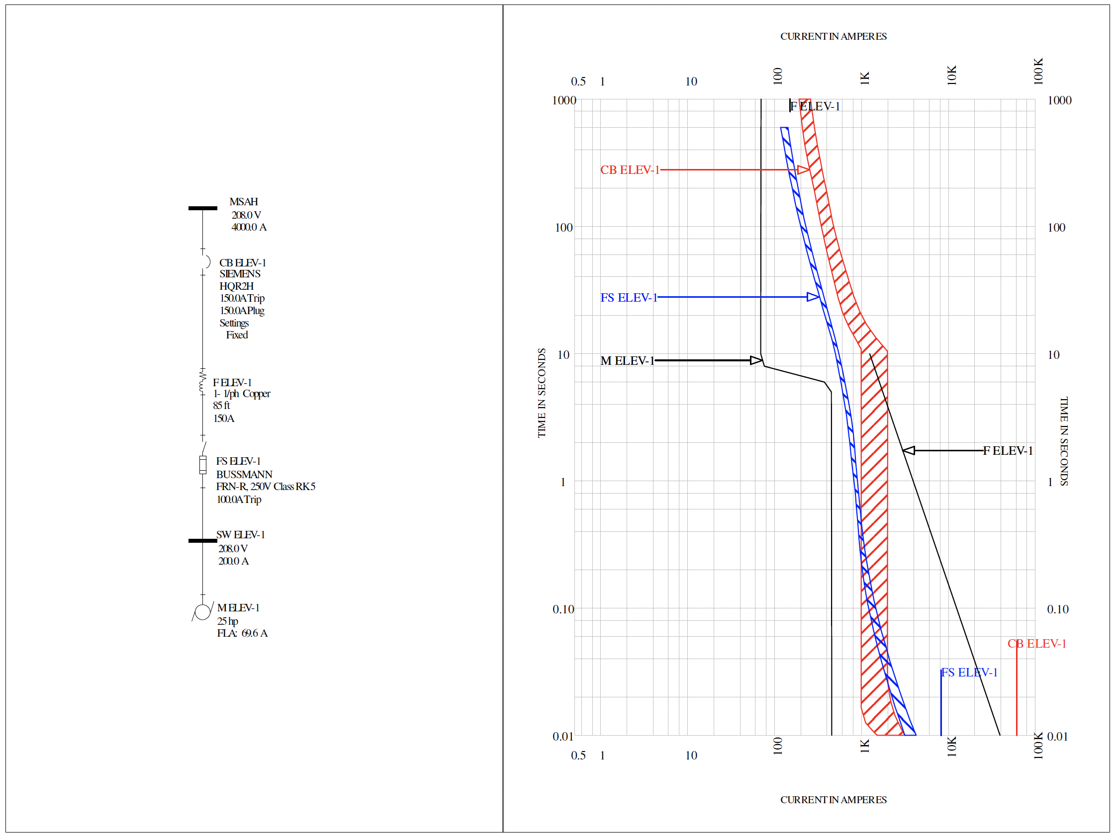
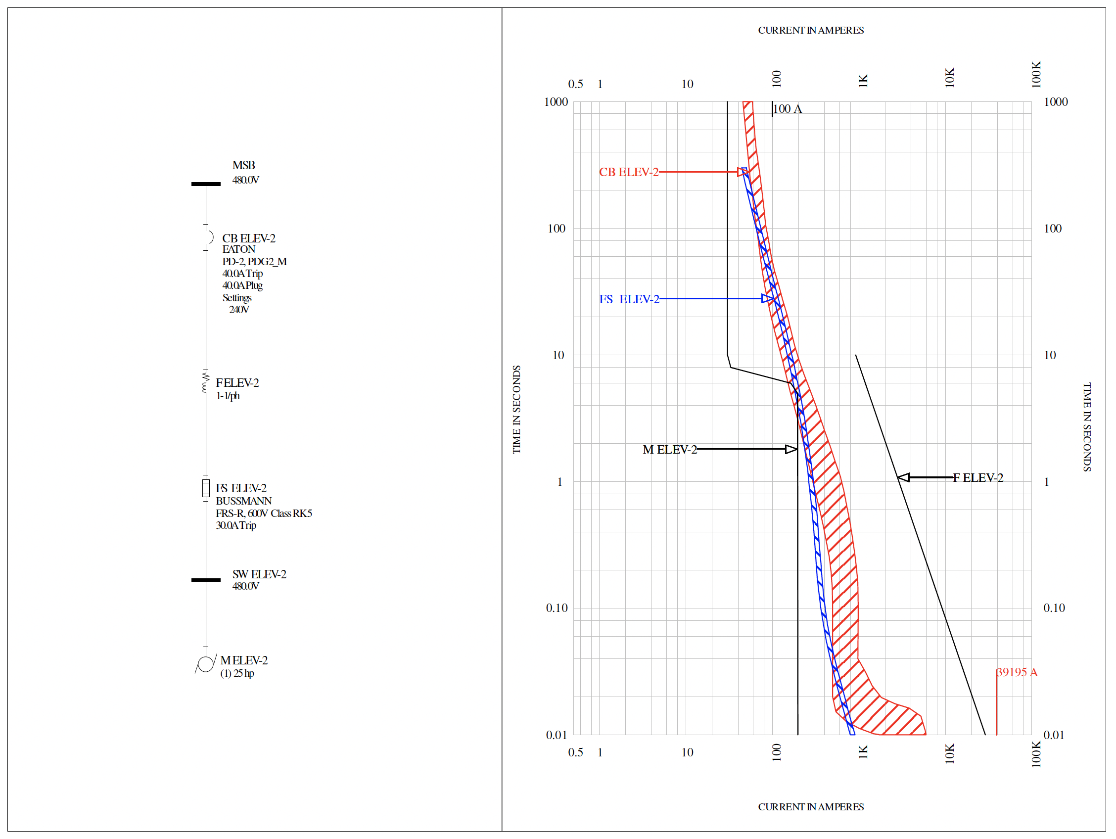
Coordination of Protective DevicesTo coordinate an overcurrent relay with other protective devices, a minimum time margin must exist between the curves. This time margin can account for several things, including the circuit breaker clearing time, the tolerances of the circuit breaker and the relay, maintenance practices, and the effects of mild current transformer saturation. Relay Time Margins0.2-0.35 seconds: Time margin between relays0.08 seconds (5 cyc): Breaker clearing time 0.12-0.17 seconds: Safety Margin *0.1 secondsWehn coordinating electro-mechanical (EM) relays, and addition 0.21 seconds should be added for induction disc over-travel. FuseTime Margins0.2-0.35 seconds: Time margin between relays0.08 seconds (5 cyc): Breaker clearing time 0.12-0.17 seconds: Safety Margin *0.1 secondsWehn coordinating electro-mechanical (EM) relays, and addition 0.21 seconds should be added for induction disc over-travel. Time-Current Curve (TCC)Coordination is demonstrated by plotting the TCC curves of circuit breakers involved and by making sure that the curve of the circuit breakers don't overlap. In the Protective Device Coordination analysis, we plot the time-current characteristics of the equipment within the scope of work onto a series of Time-Current Characteristic (TCC) curve sets. The TCCs are presented as log-log graphs, illustrating the device's operating time versus current. The fault current is plotted on the horizontal axis, and the device's tripping time is plotted on the vertical axis. The curve typically consists of multiple segments, each corresponding to a different operating characteristic or protective element of the circuit breaker. These segments may include long-time delay, short-time delay, and instantaneous trip. Starting with the device closest to the source, we systematically plot the TCCs with the aim of preserving an adequate coordination interval between devices in series. By analyzing the TCC curve, engineers and electricians can assess the coordination between circuit breakers in a system. It helps determine if the circuit breakers are appropriately coordinated to ensure selectivity, where only the closest breaker to the fault operates while minimizing the impact on the rest of the system. It also aids in identifying potential issues such as inadequate coordination, overlapping curves, or gaps in protection. 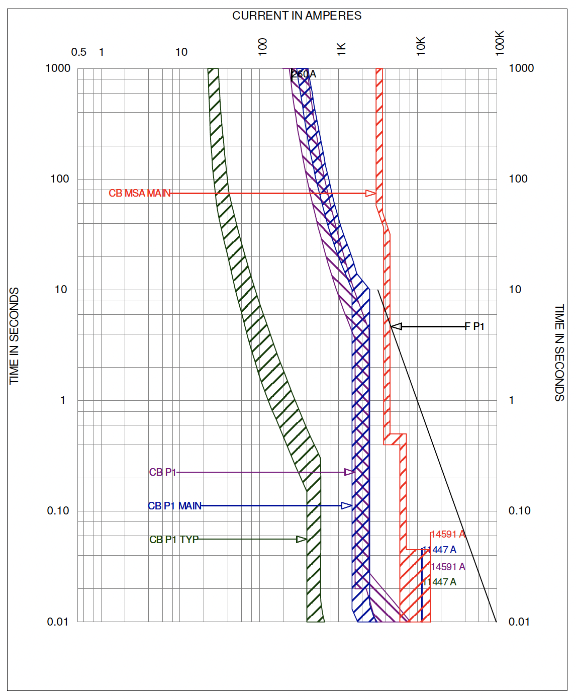
Circuit Breaker SettingsThermal Magnetic BreakersThermal Magnetic Breakers only have two forms of protection, time over current, also referred to as longtime, and instantaneous. Nuisance tripping, or unwanted tripping of protection might occur if inrush current reaches into the primary protection's curve trip area. Long-Time Pick-up (LTPU), or Continuous Amps rating (Ir) , is a multiple of the breaker's nominal (In) or frame rating. This setting dial usually has a range from 0 to 1 , with 10% (.10) increments. This setting determines the threshold current level at which the breaker will trip after a prolonged period of time. 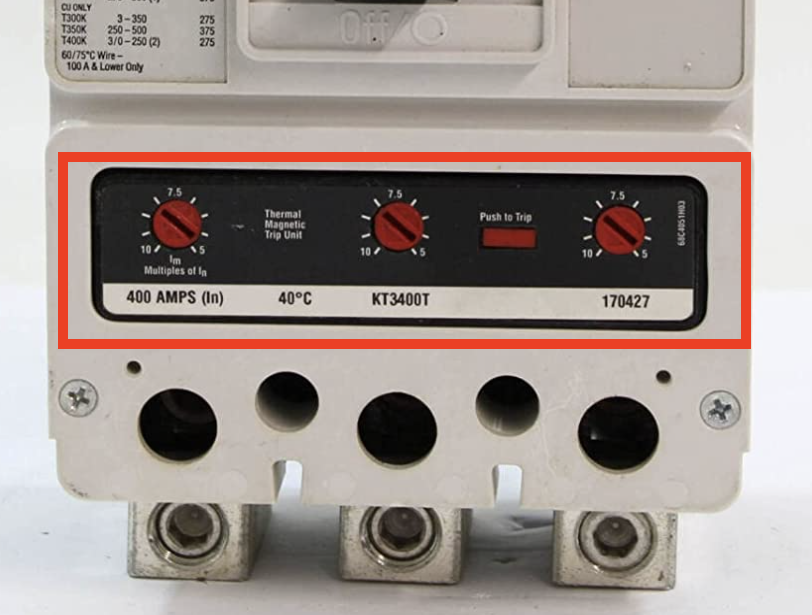
Instantaneous , or magnetic trip element protects against hign current faults. On MCCB, this element can be fixed or adjustable. Instantaneous trip value is a multiple of the breaker's current rating, usually 10 times the Frame rating ( Ir). should be checked by selecting suitable current to ensure that the breaker magnetic feature is working. The difficulty in conducting this test is the availability of obtaining the required high value of test current. Electronic Trip unit (ETU)Circuit breakers with electronic trip units provide advanced protection features and settings to ensure the safety and reliability of electrical systems. The electronic trip unit (ETU) is responsible for monitoring the current flowing through the circuit and tripping the breaker if certain conditions are met. Here are some common protection settings found in electronic trip units: 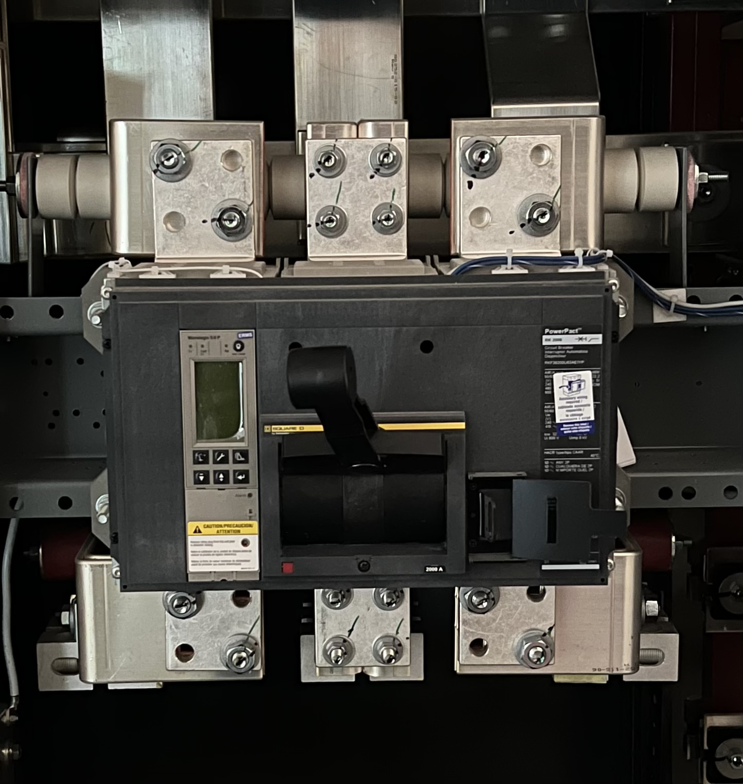
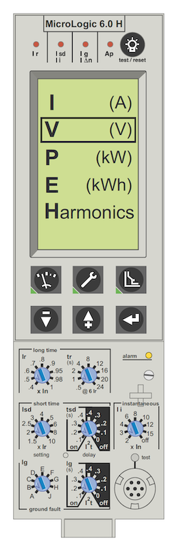
Long Time Protection
Long-time protection is crucial for safeguarding the electrical system against sustained overloads or faults that may cause excessive heating and damage to conductors and connected devices. It is commonly used to protect against continuous overcurrent situations that might occur due to: High levels of current drawn by a faulty device or equipment. Prolonged overloads that may occur during abnormal operating conditions. Faults in the electrical system that persist for an extended period. Long-Time Pick-up (LTPU), or Continuous Amps rating (Ir) , is a multiple of the breaker's nominal (In) or frame rating. This setting dial usually has a range from 0 to 1 , with 10% (.10) increments. Long-Time Pickup (LTP): This setting determines the threshold current level at which the breaker will trip after a prolonged period of time. Most electronic breakers have a pick-up indicator light, usually located on the front of the breaker. A Pick-up indicator light usually turns on when current flowing through the breaker reaches a magnitude within 5-10% of the breaker's current rating. 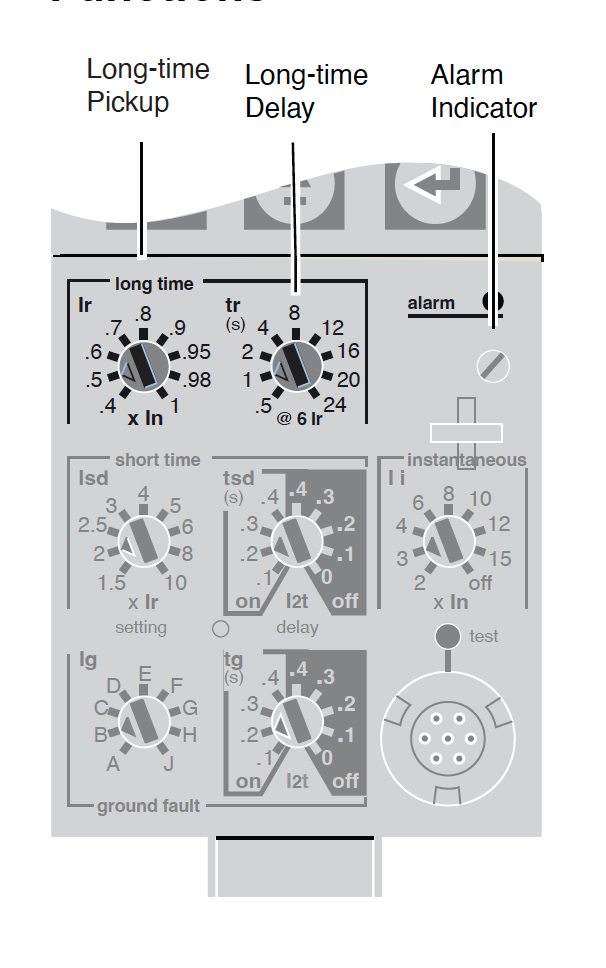
Long-Time Delay (LTD) element sets a length of time that the circuit breaker will carry a sustained overload before tripping. This test verifies the breaker's overload trip characteristic (i.e., time–current relationship), by selecting a percentage of breaker current rating, such as 300%, and applying this current to each of the breaker's poles and measuring the time the
Short Time Protection
Short-Time Pick-Up (STPU) setting determines the threshold current level at which the short-time protection feature becomes active. When the current exceeds this threshold, the short-time protection function is initiated. It is a percentage of the circuit breaker’s nominal rating (In ) . Short-Time Delay (STD) setting specifies the time delay before the circuit breaker trips in response to an overcurrent condition. This delay is intentional and allows the breaker to tolerate brief overcurrent conditions that might be part of normal system operation. 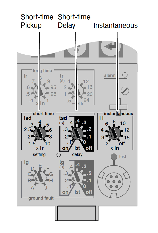
The short-time protection is particularly useful for handling short-duration overcurrent events, such as those caused by motor starting, transformer inrush currents, or other transient conditions. By selectively tripping the circuit breaker for these short-duration faults, the system can operate more efficiently and avoid unnecessary disruptions.
Instantaneous Protection
Instantaneous Pick-Up sets the current level at which circuit breaker will trip with no intentional time delay. The Instantaneous current (Ii ) I equal to the Instantaneous pick-up setting multiplied by the sensor plug amperage(In ). point is a percentage of the circuit breaker’s nominal rating (In ), not the rating plug multiplier (Ir ) . The Instantaneous function will override the short-time function if the instantaneous pickup is set at the same or lower setting than the short-time pickup. 
Ground Fault
Ground Fault Pick-Up (GFPU) sets the current level at which circuit breaker will trip after the set Ground Fault time delay. Ground Fault pick up values (Ig ) point is a percentage of the circuit breaker’s nominal rating (In ), not the rating plug multiplier (Ir ) . Ground Fault Delay (GFD) sets the length of time the circuit breaker will carry ground-fault current which exceeds the Ground Fault pick up level before tripping. The delay, based on the sensor plug amperage (In ), can be adjusted to four positions of I2tramp operation (I2t) ON or five position of fixed time delays (I2t OFF). (I2t) ON is an "inverse time" characteristic. This means the time-delay decreases as the current increases. 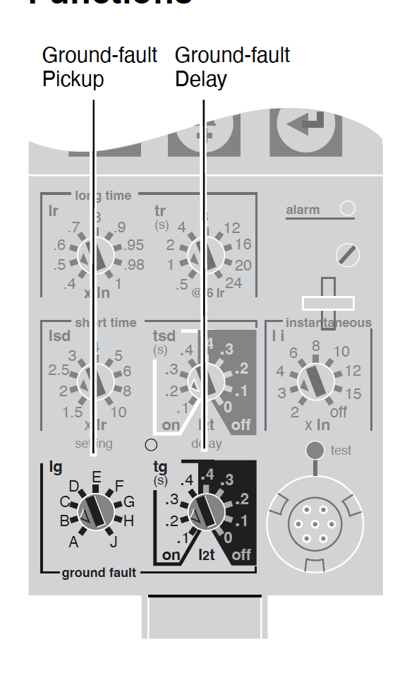
Glossary of Terms
NEC 70 Articles
|
|
| Cable Protection | |
|---|---|
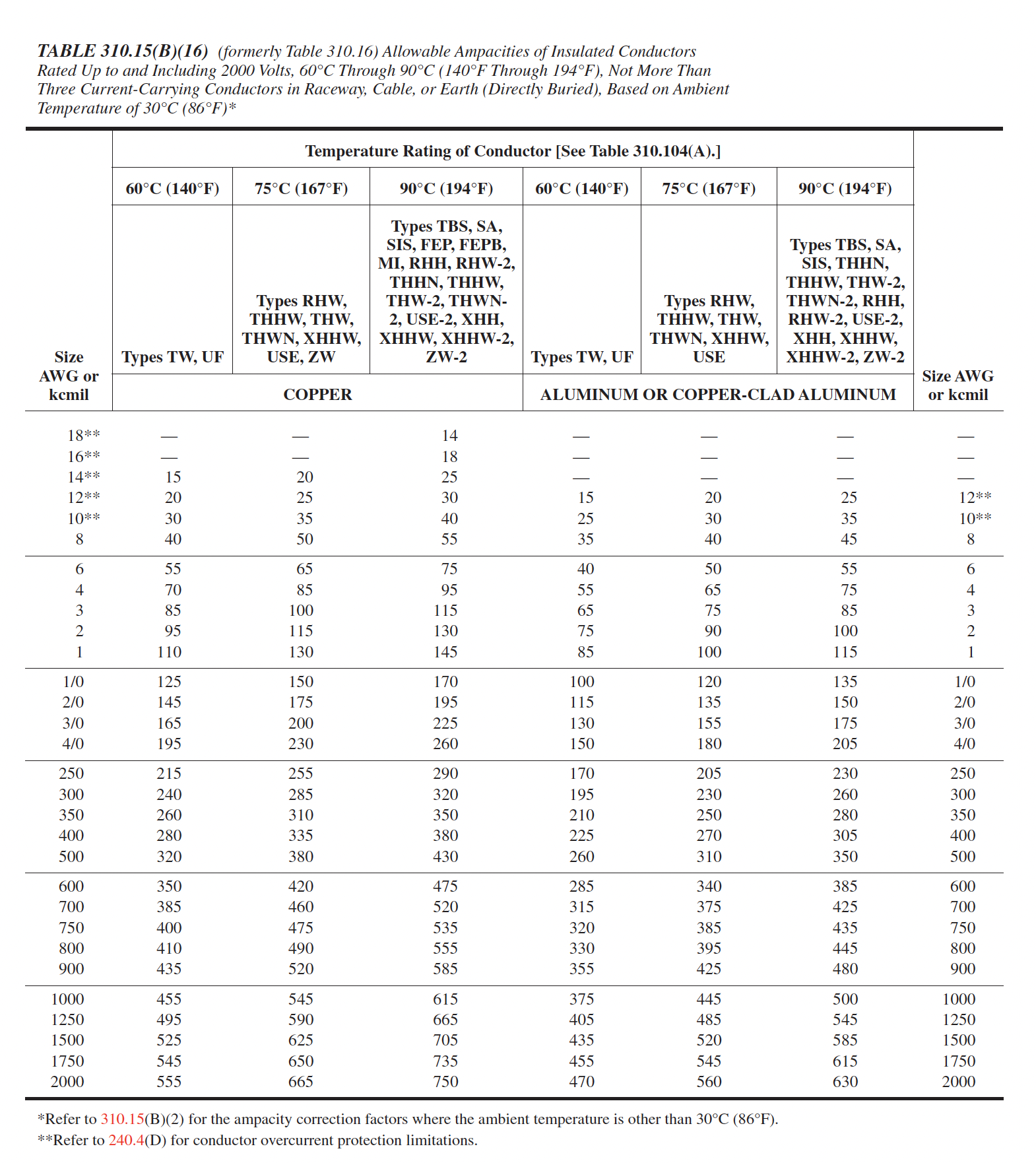
Cable AmpacityStep 1 Refer to NEC Table 310.15(B)(16)Locate NEC Table 310.15(B)(16) in the 2015 NEC code book. This table provides the ampacity for conductors rated 0-2000 volts. Identify the type of insulation (THHN) and the temperature rating of the insulation. THHN typically has a 90°C (194°F) temperature rating. Step 2: Determine the Ampacity from the TableIn Table 310.15(B)(16), locate the row for 4/0 AWG.
Under the 90°C (194°F) column, find the corresponding ampacity for THHN insulation. Step 3: Apply Ambient Temperature Correction Factors
Step 4: Apply Adjustment Factors for More Than Three Current-Carrying Conductors
NEC 70-2023
Article 310.15, Ampacities of Insulated Conductors Rated 0–2000 Volts 310.15 Ampacities for Conductors Rated 0–2000 Volts
(1) Tables or Engineering Supervision.
(2) Selection of Ampacity.
Exception:
NEC 70 Tables 310.15(B)16
Transformer Protection (Less than 1000V)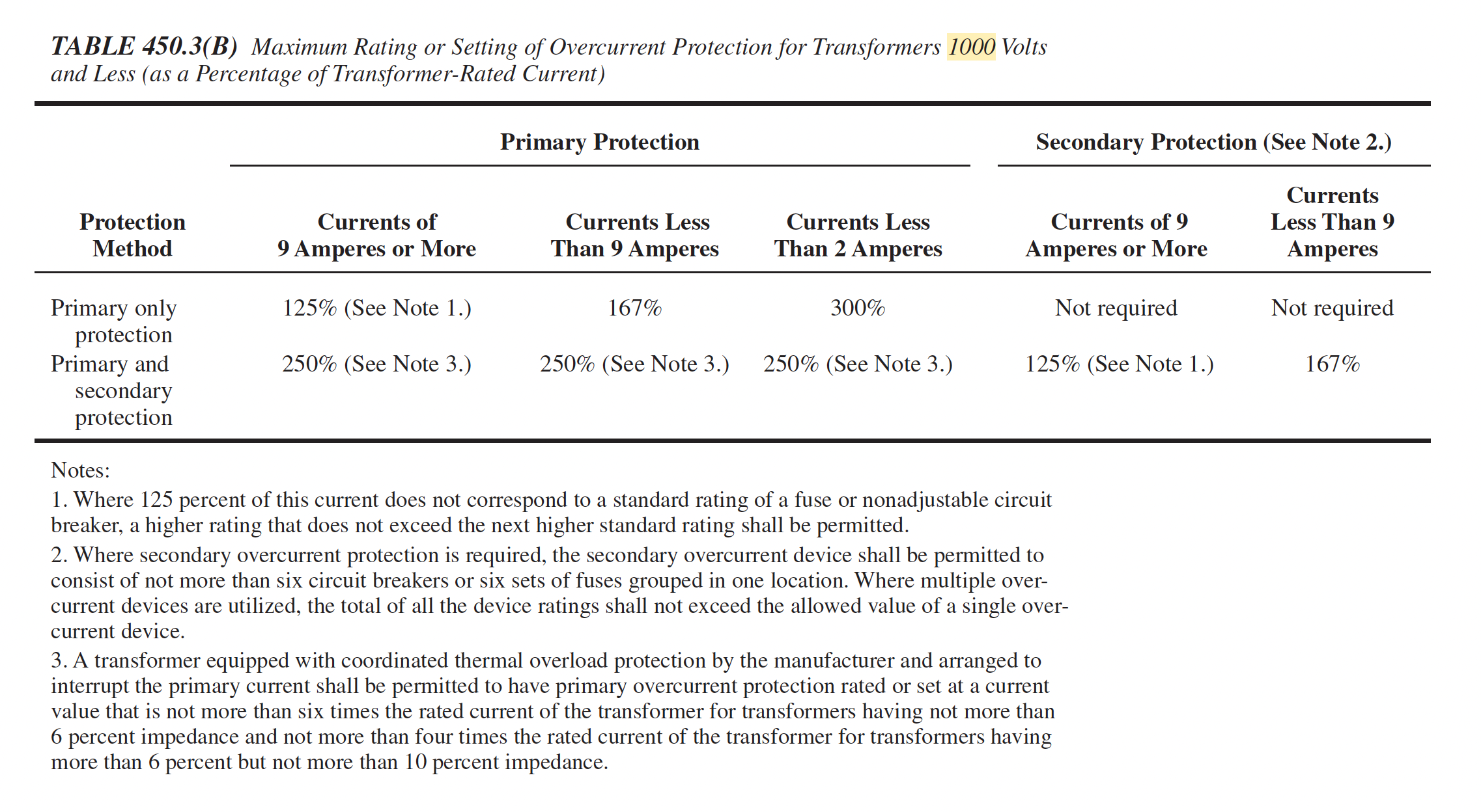
Cable ProtectionPower cables require overload and short-circuit protection in order to meet the requirements stated in NEC Article 240, and IEEE Std 242. Low voltage cable protection (0-2000 Volts) is determined by NEC Article 310.15. Cable de-rating based on ambient temperature and the number of current-carrying conductors in a raceway must also be applied. Medium voltage cable protection (2001-35,000 Volts) ampacity is defined by NEC Articles 240.100(A) and 310.60.
NEC 70-2023
Article 240.4 Protection of Conductors 240.4 Protection of ConductorsConductors, other than flexible cords, flexible cables, and fixture wires, shall be protected against overcurrent in accordance with their ampacities specified in 310.15, unless otherwise permitted or required in 240.4(A) through (G).
(A) Power Loss Hazard.
(B) Overcurrent Devices Rated 800 Amperes or Less.
(C) Overcurrent Devices Rated over 800 Amperes.
(D) Small Conductors.
(F) Transformer Secondary Conductors.
(G) Overcurrent Protection f or Specific Conductor Applications.
NEC 70-2023
Article 310.15, Ampacities of Insulated Conductors 310.15 Ampacities for Conductors Rated 0–2000 Volts
(1) Tables or Engineering Supervision.
(2) Selection of Ampacity.
Exception:
NEC 70-2023
Table 240.100(A), Overcurrent Protection of Conductors over 1000 Volts, Nominal 240.100 Feeders and Branch Circuits
(A) Location and Type of Protection.
(C) Conductor Protection 240.100 Feeders and Branch Circuits
(A) Rating or Setting of Overcurrent Protective Devices.
(B) Feeder Taps.
NEC 70-2023
Table 240.100(A), Overcurrent Protection of Conductors over 1000 Volts, Nominal 240.100 Feeders and Branch Circuits
(A) Location and Type of Protection.
(C) Conductor Protection 240.100 Feeders and Branch Circuits
(A) Rating or Setting of Overcurrent Protective Devices.
(B) Feeder Taps. Glossary of Terms
NEC 70 Articles
|
|
| Transformer Protection & Coordination | |
|---|---|
Transformer ProtectionA transformer is recommended to have protective devices on both primary and secondary side in order to meet the basic protection requirements for overloads and short-circuit withstand values. However, a transformer is permitted to be protected by only a primary side device if it meets the exceptions listed in NEC Article 240.4(F).
NEC protection requirements for transformers: Paragraph (A) specifies that transformers over 600 V comply with Table 450.3(A). Paragraph (B) specifies that transformers less than 600 V comply with Table 450.3(B).
Short-circuit thermal limits for transformers:
NEC 70, Article 450.3(A)
Overcurrent Protection Requirements NEC 450.3 Overcurrent ProtectionOvercurrent protection of transformers shall comply with 450.3(A), (B), or (C). As used in this section, the word transformer shall mean a transformer or polyphase bank of two or more single-phase transformers operating as a unit. NEC 450.3(A) Overcurrent Protection(A) Transformers Over 1000 Volts, Nominal. Overcurrent protection shall be provided in accordance with Table 450.3(A). NEC 450.3(B) Overcurrent Protection(B) Transformers 1000 Volts, Nominal, or Less. Overcurrent protection shall be provided in accordance wi th Table 450.3(B).
NEC 70 Table 450.3(A) & (B)
Transformer Protection (Greater than 1000V)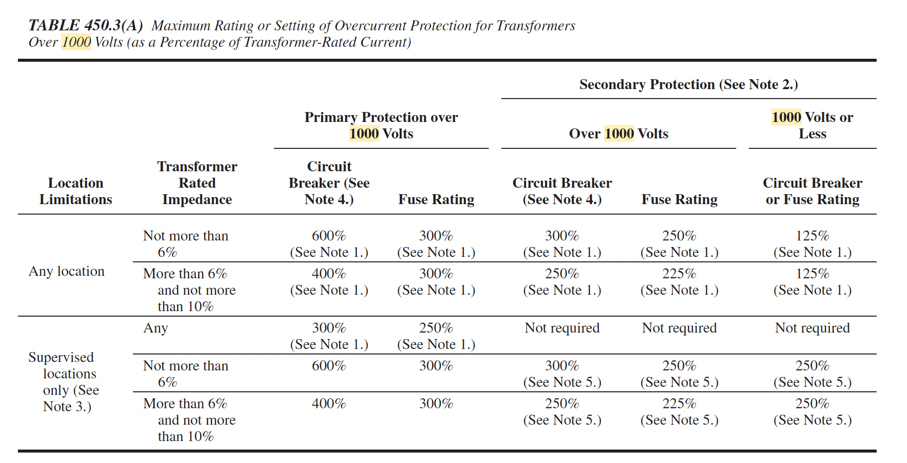
This table has two “conditions” that affect its application. One is whether or not the installation can be considered supervised. Note 3 states “where conditions of maintenance and supervision assure that only qualified persons will monitor and service the installation..." “Supervised” is more than just having a qualified person install the system. The implication of supervised means that qualified persons are on-site at all times and available to deal with any circumstances that arise with the transformer installation. Before applying these rules, the engineer or designer should contact the authority having jurisdiction to agree that the installation will meet this condition. The other condition relates to the impedance of the involved transformer. This information can be obtained from the transformer manufacturer.
Transformer Protection (Less than 1000V)
These rules apply to transformers where both the primary and secondary are 600 V or less. Table 450.3(B) outlines the requirements for protection of the transformer using a device on the primary only and protection using both primary and secondary protection. Remember, this only covers the transformer, not the conductors. Transformer InrushTransformer inrush current refers to the excessive current that flows through a transformer's windings when it is first energized. Characteristics of Transformer Inrush Current: Magnitude: It can be several times greater than the transformer's rated full-load current, typically 6 to 10 times, but can go up to 25 times or more in extreme cases. Duration: The inrush current is transient and typically lasts for a few cycles to a few seconds until the core's magnetic flux settles into its normal operating point. Impact on Systems: It can cause voltage drops, impact the operation of protective devices, and can be mistaken for fault conditions. To manage transformer inrush current, power engineers may use controlled switching strategies, pre-magnetization techniques, or specify transformers with inrush current limiting characteristics. It's important to consider inrush current in the design and operation of power systems to ensure reliable and safe operation. To manage transformer inrush current, power engineers may use controlled switching strategies, pre-magnetization techniques, or specify transformers with inrush current limiting characteristics. It's important to consider inrush current in the design and operation of power systems to ensure reliable and safe operation.
TCC with acceptable coordination
TCC below shows proper coordination between primary protection fuse and inrush curve marker; no overlap. Secondary protection coordination is not affected by inrush current. 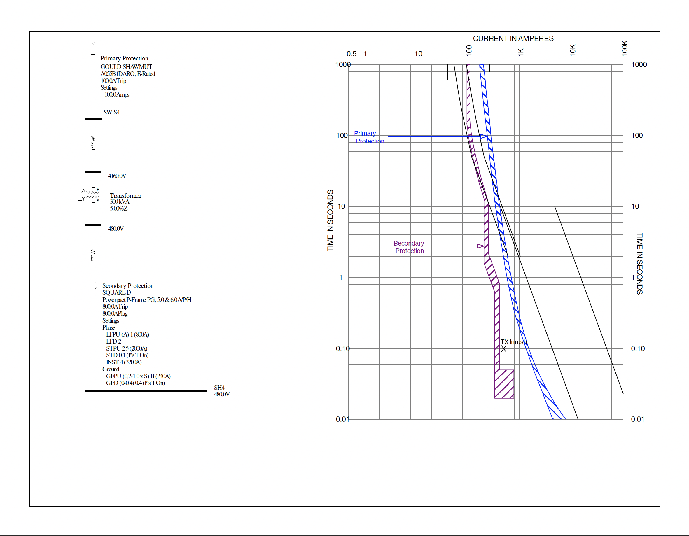
TCC showing nuisance tripping
TCC below shows overlap between primary protection curve (red) and inrush current marker. Inrush current has reached into primary protection's curve area. 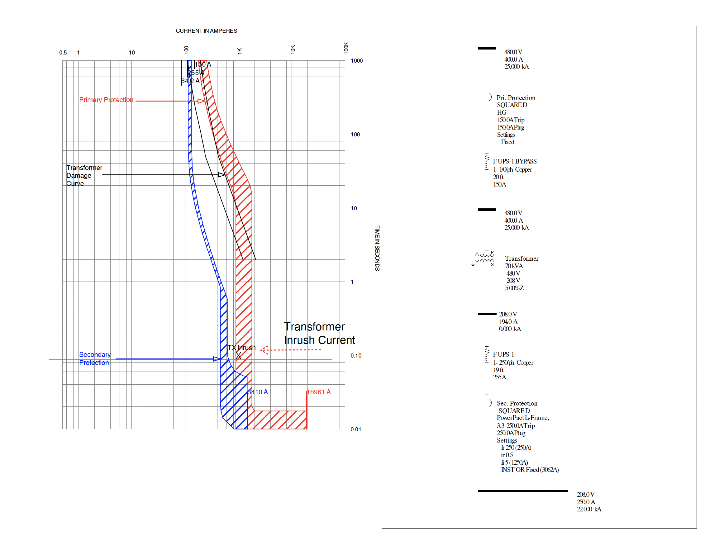
Reference Material
1, 1.5, 2, 3, 5, 7.5, 10, 15, 20, 25, 30, 40, 50, 60, 75, 100, 125, 150, 200, 250, 300, 350, 400, 450, 500, 600, 700, 800, 900, 1000, 1250, 1500, 1750, 2000, 2250, 2500, 3000, 3500, 4000. HVAC
HVAC Name plate
Make-Up Air UnitA make-up air unit is one of multiple air handling units (AHU) that HVAC contractors work with and maintain. An AHU is a device used to regulate and circulate air as part of a heating, ventilating, and air-conditioning (HVAC) system. An air handler is usually a large metal box containing a blower, heating or cooling elements, filter racks or chambers, sound attenuators, and dampers. Air handlers usually connect to a ductwork ventilation system that distributes the conditioned air through the building and returns it to the AHU. Sometimes AHUs discharge (supply) and admit (return) air directly to and from the space served without ductwork.
Terminology
MCA Minimum Circuit AmpacityMCA for both fan-powered and heater-only products is calculated with the following equation: MCA = 1.25 x [Motor Rated Current + Heater Current] The “Motor Rated Current” is sometimes referred to as the FLA (full load amps) of the unit. This can be a source of confusion because this rated current is not the same as the motor FLA shown on the nameplate of the motor itself. Our “Motor Rated Current” is determined during worst-case, high-current test conditions of the complete terminal unit, in accordance with UL1995. The FLA on the motor nameplate is a rating from the motor manufacturer and is of no use in our calculations. Motor Rated Current values for current Titus products are shown in our catalog or by clicking “Titus Motor Amps” on the calculator screen. MOP Maximum Overcurrent ProtectionMOP is a bit more complicated. First, a basic calculation is made, and then a number of filters or conditions will alter the computed MOP value to arrive at the final value that appears on a product nameplate. In short, the basic MOP is calculated by multiplying the rated current of the largest motor times 2.25, and adding in all other loads of 1.0 amp or more that could be in operation at the same time. MOP = [2.25 x (Rated Current of Largest Motor)] + (Other Motor Loads) + (All Heater Loads) Filter 1: If the MOP value is not an even multiple of 5, the MOP is rounded down to the nearest standard fuse size. Filter 2: If the MOP is less than the MCA, the MOP is made equal to the MCA and then rounded up to the nearest standard fuse size, typically a multiple of 5. In other words, the MOP shall not be less than the MCA. Final Filter 3: If the MOP is less than 15, it shall be rounded up to 15 amps. This is the minimum size of fuse or circuit breaker permitted by code. |
|
| Motor Protection & Coordination | |
|---|---|
Motor ProtectionThe NEC (National Electrical Code) outlines specific requirements for overload and short-circuit protection to ensure the safety and reliability of motor branch circuits. These requirements are designed to prevent damage to the motor and associated equipment, as well as to reduce the risk of fire. Here are the key NEC requirements for overload and short-circuit protection:
Overload Protection: NEC overload sizing specifications:Service Factor > 1.15 : Overload should be sized between 115% to 125% of the motor's full-load current Service Factor = 1.0 : Overload should be sized 115% of the motor's full-load current
Short-Circuit and Ground-Fault Protection: The sizing of short-circuit and ground-fault protection devices must comply with the NEC's specific rules, which consider the motor's starting characteristics, including locked rotor currents, and ensure that the protection device does not nuisance trip during motor start-up. The sizing typically involves ensuring the device's rating or setting does not exceed the maximum permitted values outlined in the NEC tables for the specific type of motor and the conditions of use. The National Electrical Code (NEC) outlines specific requirements for motor branch circuit protection in various articles and tables. The most relevant ones include: Article 430 - Motors, Motor Circuits, and Controllers:This is the primary article in the NEC that covers the requirements for motors, motor circuits, and the associated control equipment. It provides comprehensive coverage of the topics related to motor installation, including protection against overloads, short circuits, and ground faults. Tables in Article 430:
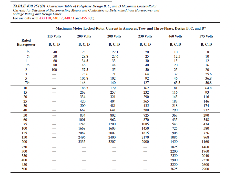
Table 430.52
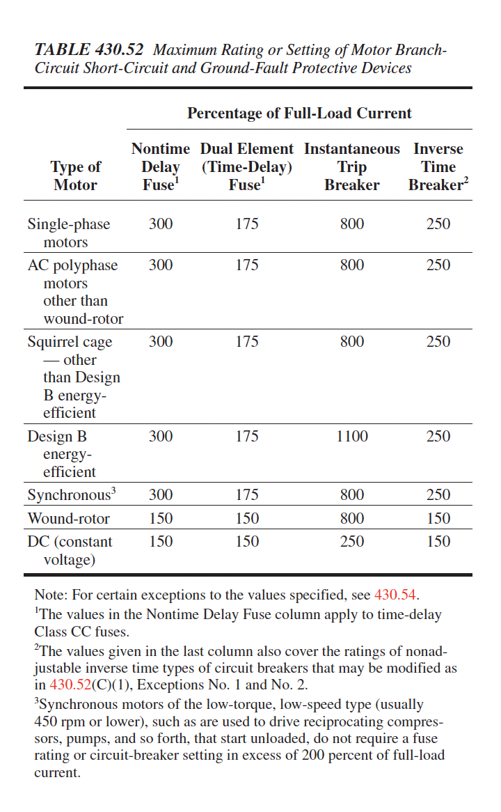
Table 430.250
Table 430.147, 430.148, and 430.150 Article 240 - Overcurrent Protection:While Article 430 provides specific requirements for motors, Article 240 covers general requirements for overcurrent protection. It includes provisions that apply to motor circuits, such as the sizing and installation of overcurrent protective devices. Article 310 - Conductors for General Wiring:This article includes information relevant to the conductors used in motor circuits, including conductor sizing and insulation types.
NEC 430.32 Continuous-Duty Motors
430.32 Continuous-Duty Motors(A)(1) Separate Overload Device. A separate overload device that is responsive t o motor current. This device shall be selected to trip or shall be rated at no more than the following percent of the motor nameplate full-load current rating: Motors with a marked service factor 1.15 or greater 125% Motors with a marked temperature rise 40°C or less 125% All other motors 115%
NEC 430.24 Several Motors or a Motor(s) and Other
Load(s)
NEC 430.24 Several Motors or a Motor(s) and Other Load(s) Conductors supplying several motors, or a motor(s) and other load(s), shall have an ampacity not less than the sum of each of the following: (1) 125 percent of the full-load current rating of the highest rated motor, as determined by 430.6(A) (2) Sum of the full-load current ratings of all the other motors in the group, as determined by 430.6(A) (3) 100 percent of the noncontinuous non-motor load (4) 125 percent of the continuous non-motor load.
NEC TABLE 310.16 Ampacities of Insulated Conductors
NEC Table 310.16Allowable Ampacities of Insulated Conductors Rated Up to and Including 2000 Volts, 60°C Through 90°C (140°F Through 194°F), Not More Than Three Current-Carrying Conductors in Raceway, Cable, or Earth (Directly Buried), Based on Ambient Temperature of 30°C (86°F)* 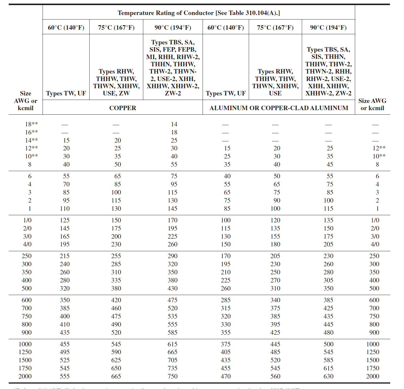
Motor Inrush CurrentMotor inrush current, also known as starting current or surge current, refers to the initial surge of current into an electric motor when it is first energized. This phenomenon occurs because when an AC motor starts, it does not immediately begin to rotate. The stationary rotor presents a very low impedance path, resulting in a large current draw as the motor begins to turn. Magnitude of Current: The inrush current can be significantly higher than the motor's normal operating current, often exceeding it by more than 20 times during the initial half-cycle of power application. This value then gradually decreases to a level of about 4 to 8 times the normal current for several seconds, before settling down to the normal running current as the motor reaches its operating speed. Duration: The inrush current is a transient condition lasting only a few seconds as the motor accelerates up to its rated speed. Impact on Systems: This high current can impact electrical systems by causing voltage drops and triggering protective devices like fuses or circuit breakers, potentially leading to nuisance trips. Fire Pump ProtectionFire pumps are a critical component in the fire protection systems of buildings, especially in structures that are high-rise, large, or otherwise at significant risk of fire. They are designed to supply water at a high pressure to fire sprinkler systems and other fire suppression devices, ensuring that in the event of a fire, there is sufficient water flow and pressure to combat the flames effectively. The reliability and functionality of fire pumps can be the difference between minor damage and a catastrophic loss in the event of a fire. Supervising electric motor-driven fire pump circuits is a crucial aspect emphasized in the National Electrical Code (NEC) to ensure that fire pumps remain operational during emergencies. The NEC provides specific guidelines to prevent inadvertent disconnection of these critical circuits, whether they are connected directly or through a disconnecting means and an overcurrent protection device. The primary objective is to maintain continuous operation of fire pumps by providing them with a reliable power source that is secure against unintentional interruptions. NEC Article 695 - Fire PumpsKey Aspects of Fire Pump Circuit Supervision:
Direct Connection (695.4(A)):
Disconnecting Means (695.4(B)):
Overcurrent Protection (695.4(B)(2)):
NEC 70-2023 695.4, Continuity of Power
Article 695.4(A), Direct Connection. 695.4 Continuity of Power.Circuits that supply electric motor–driven fire pumps shall be supervised from inadvertent disconnection as covered in 695.4(A) or (B). (A) Direct Connection.The supply conductors shall directly connect the power source to a listed fire pump controller, a listed combination fire pump controller and power transfer switch, or a listed fire pump power transfer switch.
NEC 70-2023
Article 695.4(B), Connection Through Disconnecting Means and Overcurrent Device. 695.4 Continuity of Power.(B) Connection Through Disconnecting Means and Overcurrent Device.(1) Number of Disconnecting Means. (a) General: A single disconnect ing means and associated overcurrent protective device(s) shall be permitted to be installed between the fire pump power source(s) and one of the following: [20:9.1.2]
(b) Feeder Sources: For systems installed under the provisions of 695.3(C) only, additional disconnecting means and the associated overcurrent protective device(s) shall be permitted as required to comply with other provisions of this Code. (c) On-Site Standby Generator: Where an on-site standby generator is used to supply a fire pump, an additional disconnecting means and an associated overcurrent protective device(s) shall be permitted. (2) Overcurrent Device Selection. Overcurrent devices shall comply with 695.4(B)(2)(a) or (b). (a) Individual Sources: Overcurrent protection for individual sources shall comply with 695.4(B)(2)(a)(1) or (2). (1) Overcurrent protective device(s) shall be rated to carry indefinitely the sum of the locked-rotor current of the largest fire pump motor and the pressure maint enance pump motor(s) and the full-load current of all of the other pump motors and associated fire pump accessory equipment when connected to this power supply. Where the locked rotor current value does not correspond to a standard overcurrent device size, the next standard overcurrent device size shall be used in accordance with 240.6. The requirement to carry the locked-rotor currents indefinitely shall not apply to conductors or devices other than overcurrent devices in the fire pump motor circuit(s). [20:9.2.3.4] (2) Overcurrent protection shall be provided by an assembly listed for fire pump service and complying with the following:
(b) On-Site Standby Generators.: Overcurrent protective devices between an on-site standby generator and a fire pump controller shall be selected and sized to allow for instantaneous pickup of the full pump room load, but shall not be larger than the value selected to comply with 430.62 to provide shortcircuit protection only. [20:9.6.1.1] HVAC
Motor protection Sizing Example
Sizing Motor protection and conductor ratings
Step 1 Identify Motor FLA Value 5HP 480VFLA: 7.6A 40HP 480V
FLA: 52A
Step 2 Calculate Overload Rating 7.6A x 125% =9.5A 52A x 125% =65A
Step 3 Calculate conductor Size Rating #14 #6
Step 4 Feeder Protection 7.6A * 250% = 19A 52A * 250% = 130A
Step 5 Feeder feeding both circuits (125%*52A)+7.6 = 72.6A Size per table is #4
Step 6 protection for step 5 feeder 150A +7.6A= 157.6A Must go down in size to 150A breaker
NEC 430.32 Continuous-Duty Motors
430.32 Continuous-Duty Motors(A)(1) Separate Overload Device. A separate overload device that is responsive t o motor current. This device shall be selected to trip or shall be rated at no more than the following percent of the motor nameplate full-load current rating: Motors with a marked service factor 1.15 or greater 125% Motors with a marked temperature rise 40°C or less 125% All other motors 115%
NEC 430.24 Several Motors or a Motor(s) and Other
Load(s)
NEC 430.24 Several Motors or a Motor(s) and Other Load(s) Conductors supplying several motors, or a motor(s) and other load(s), shall have an ampacity not less than the sum of each of the following: (1) 125 percent of the full-load current rating of the highest rated motor, as determined by 430.6(A) (2) Sum of the full-load current ratings of all the other motors in the group, as determined by 430.6(A) (3) 100 percent of the noncontinuous non-motor load (4) 125 percent of the continuous non-motor load.
NEC TABLE 310.16 Ampacities of Insulated Conductors
NEC Table 310.16Allowable Ampacities of Insulated Conductors Rated Up to and Including 2000 Volts, 60°C Through 90°C (140°F Through 194°F), Not More Than Three Current-Carrying Conductors in Raceway, Cable, or Earth (Directly Buried), Based on Ambient Temperature of 30°C (86°F)*
Reference Material
1, 1.5, 2, 3, 5, 7.5, 10, 15, 20, 25, 30, 40, 50, 60, 75, 100, 125, 150, 200, 250, 300, 350, 400, 450, 500, 600, 700, 800, 900, 1000, 1250, 1500, 1750, 2000, 2250, 2500, 3000, 3500, 4000. HVAC
HVAC Name plate
Make-Up Air UnitA make-up air unit is one of multiple air handling units (AHU) that HVAC contractors work with and maintain. An AHU is a device used to regulate and circulate air as part of a heating, ventilating, and air-conditioning (HVAC) system. An air handler is usually a large metal box containing a blower, heating or cooling elements, filter racks or chambers, sound attenuators, and dampers. Air handlers usually connect to a ductwork ventilation system that distributes the conditioned air through the building and returns it to the AHU. Sometimes AHUs discharge (supply) and admit (return) air directly to and from the space served without ductwork.
Terminology
MCA Minimum Circuit AmpacityMCA for both fan-powered and heater-only products is calculated with the following equation: MCA = 1.25 x [Motor Rated Current + Heater Current] The “Motor Rated Current” is sometimes referred to as the FLA (full load amps) of the unit. This can be a source of confusion because this rated current is not the same as the motor FLA shown on the nameplate of the motor itself. Our “Motor Rated Current” is determined during worst-case, high-current test conditions of the complete terminal unit, in accordance with UL1995. The FLA on the motor nameplate is a rating from the motor manufacturer and is of no use in our calculations. Motor Rated Current values for current Titus products are shown in our catalog or by clicking “Titus Motor Amps” on the calculator screen. MOP Maximum Overcurrent ProtectionMOP is a bit more complicated. First, a basic calculation is made, and then a number of filters or conditions will alter the computed MOP value to arrive at the final value that appears on a product nameplate. In short, the basic MOP is calculated by multiplying the rated current of the largest motor times 2.25, and adding in all other loads of 1.0 amp or more that could be in operation at the same time. MOP = [2.25 x (Rated Current of Largest Motor)] + (Other Motor Loads) + (All Heater Loads) Filter 1: If the MOP value is not an even multiple of 5, the MOP is rounded down to the nearest standard fuse size. Filter 2: If the MOP is less than the MCA, the MOP is made equal to the MCA and then rounded up to the nearest standard fuse size, typically a multiple of 5. In other words, the MOP shall not be less than the MCA. Final Filter 3: If the MOP is less than 15, it shall be rounded up to 15 amps. This is the minimum size of fuse or circuit breaker permitted by code. |
|
| Arc Flash Assessment Report | |
|---|---|
Arc Flash Hazard Assessment ReportAn arc flash hazard assessment report is a comprehensive document that identifies and evaluates potential arc flash hazards within an electrical system or facility. The purpose of the report is to provide essential information about the risks associated with arc flashes and recommend measures to mitigate those risks. This section of the report contains the interpretation of the arc flash incident energy analysis. The calculations conducted in this analysis align with the safety requirements found in NFPA 70E-2021.
Calculations
Both NFPA 70E and IEEE Std 1584 offer equations and methodologies for determining the arc flash boundary and incident energy at defined locations within an electrical system. These standards apply to any location where work on or near energized electrical conductors and circuit components may occur. It's crucial to understand that PPE, though a vital safeguard, constitutes the final line of defense. It's also worth noting that PPE doesn't guarantee the prevention of all injuries resulting from an arc flash. The objective of determining the necessary PPE through arc flash incident energy analysis is to establish the level of protection required to limit injuries to the onset of a second-degree burn in the event of an arc flash. This approach aims to avoid excessive protection that could lead to heat stress, reduced visibility, and restricted body movement. While the arc flash calculation procedure is rooted in the principles of NFPA 70E and IEEE Std 1584, it is a relatively recent method for determining the required PPE level. These calculations are derived from theoretical and research data involving arc current incident energy measurements conducted under controlled test conditions. Consequently, the results of calculations may be more or less severe than the hazard posed by an actual arc flash event. Furthermore, the calculations do not account for risks associated with molten metal splatter, explosively propelled equipment fragments, or air pressure shock waves.
Report Elements
Energized Work
It is imperative that only qualified electricians, well-versed in the installation and maintenance of electrical distribution equipment, undertake tasks associated with such products. It's essential to clarify that the results of the arc flash incident energy analysis do not imply that personnel are authorized to work on exposed energized equipment or circuits. OSHA 1910.333 specifies stringent restrictions on situations in which work is permitted on or near energized equipment. It dictates that live parts must be de-energized unless there are valid reasons for not doing so, such as increased hazards or infeasibility due to equipment design or operational constraints. Adherence to the manufacturer's recommendations, warnings, and cautions pertaining to personnel and equipment safety is crucial. Furthermore, strict compliance with all relevant health and safety laws, codes, standards, and procedures is essential. Prior to any maintenance or service, all equipment must be de-energized. Adhering to OSHA 1910.333 requirements is mandatory. Additionally, strict adherence to the guidelines outlined in NFPA 70E-2018 is paramount. This includes providing and wearing appropriate personal protective equipment as specified. Determining the maximum allowable incident energy while performing energized work is site-specific but typically aligns with the arc rating of the most protective available PPE (usually 40 cal/cm²), subject to adjustment based on the assessment of the site safety manager. In cases where specific site safety information is unavailable, an upper limit of 40 cal/cm² is applied.
PPE
The risk associated with arc flash exposure while working on or near electrical equipment hinges on several factors, including the nature of the task and the condition of the equipment. NFPA 70E-2023, Article 130.7(A) stipulates that employees must use, and employers must provide, suitable PPE tailored to the specific tasks at hand. Reference to NFPA 70E, Table 130.5(G) furnishes guidance on selecting PPE based on the calculated incident energy exposure. NFPA 70E-2018, Article 110.1(G) mandates that an employer-developed electrical safety program must encompass a comprehensive risk assessment procedure addressing worker exposure to electrical hazards. This procedure is a prerequisite whenever tasks involving electrical equipment at or above 50 volts are undertaken, or whenever work takes place in the presence of electrical hazards. This analysis specifically focuses on the outcomes of an incident energy evaluation conducted following 130.5(C)(1). The selection of personal protective equipment (PPE) should be driven by the incident energy level at the working distance. This critical information is provided in this report as part of an arc flash risk assessment, a process to be carried out by a qualified individual. Other aspects of the arc flash risk assessment encompass determining the existence of an arc flash hazard for a specific work task and identifying the safe work practices to be observed by the qualified personnel undertaking the work. Glossary of Terms
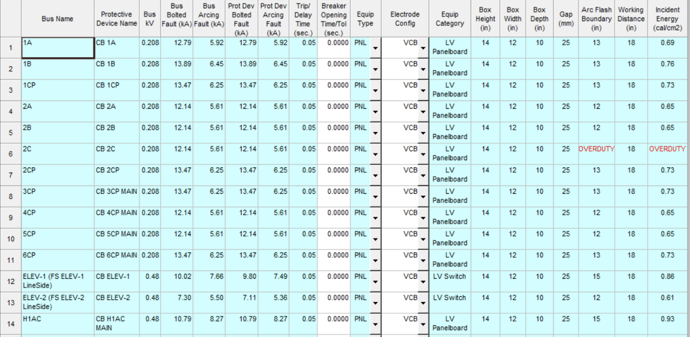
Line Side / Load Side Calculations
The “Load Side” calculation provides the incident energy based on the main protective device clearing in the event of an arc flash incident. If the work location or task is such that the main breaker may not trip in the event of an arc flash incident, then the “Line Side” calculation for incident energy should be observed. This could occur if the main breaker is being racked-out and a fault occurred on the line terminals.
NOTE: Circuit Breakers can not sense upstream or line side faults. 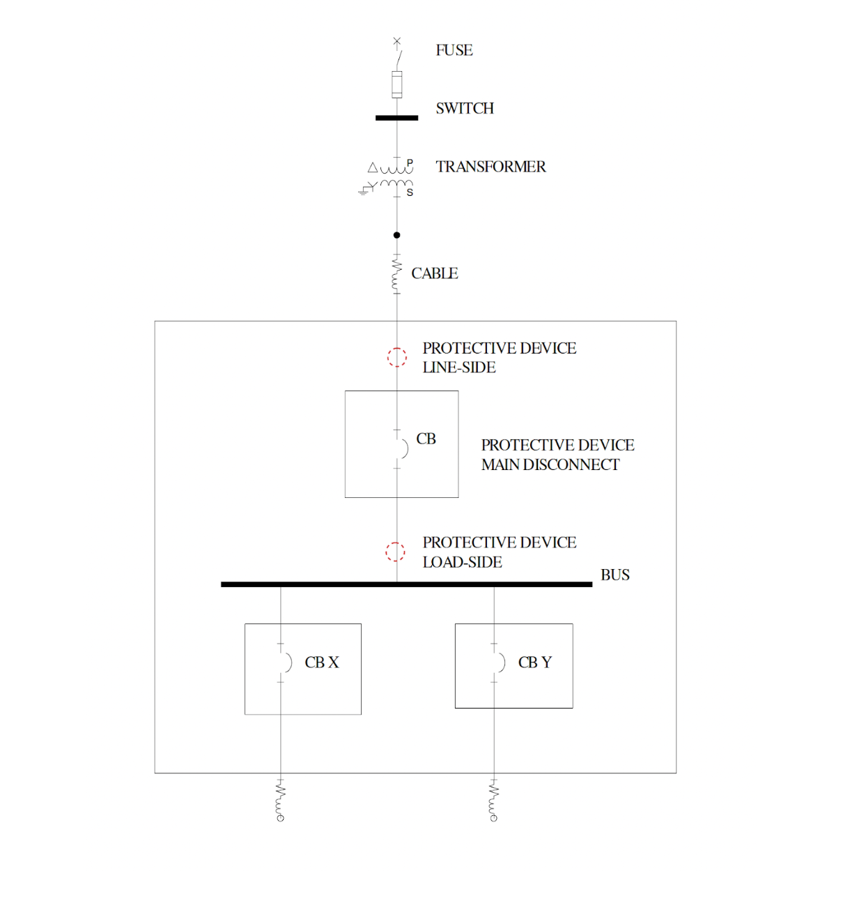
Electrode ConfigurationIEEE 1584-2018 does not provide specific recommendations for electrode configurations beyond those detailed in informative Annex C. Electrical equipment adheres to industry standards, and the determination of electrode configurations by equipment class typically applies to both new and existing equipment, irrespective of the manufacturer. When conducting a risk assessment prior to energized work, it's crucial to consider where qualified workers will interact with live conductors and how an arc flash might initiate. If a qualified worker faces an electrode configuration different from that outlined in Table 8.1, it is advisable to review the incident energy analysis to ensure its suitability for the specific task at hand. In the IEEE-1584-2018 calculation process, one or more electrode configurations are selected for each equipment location, with the worst-case results documented in Table 8.1. These configurations are chosen based on the typical construction of standard equipment classes. The selected electrode configuration is reported in Table 8.1 for each location. In cases where the physical construction of the equipment allows for multiple electrode configurations, multiple calculations are performed to determine the worst-case incident energy and arc flash boundary.
VCB VCB represents vertical conductors in a metal box or enclosure. An arc initiated on the vertical busbars will run down the bus away from the source, and the plasma cloud will be directed off the conductors' ends in a manner parallel to the enclosure opening. The direction of arc plasma is indicated by the arrow below. Note: While the name implies that conductors are oriented vertically, from top to bottom conductors that are traveling across the enclosure horizontally from left to right are also considered VCB. Any conductors running across the enclosure parallel to the opening plane are considered VCB. 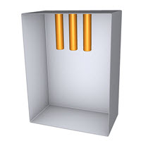
VOA 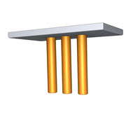
VCBB VCBB represents vertical conductors in a metal box or enclosure ending at an insulating barrier. An arc initiated on the vertical busbars will run down the bus away from the source, but the plasma cloud will reach the insulating barrier, preventing it from being directed off the ends of the conductors. Some of the arc plasma will instead be directed towards the front of the enclosure, as indicated by the arrow below.
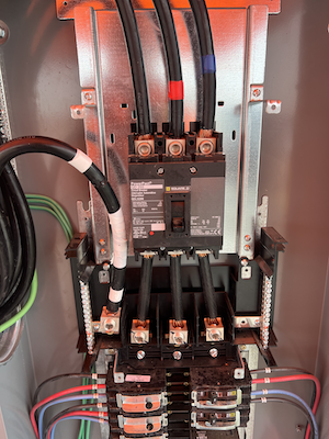
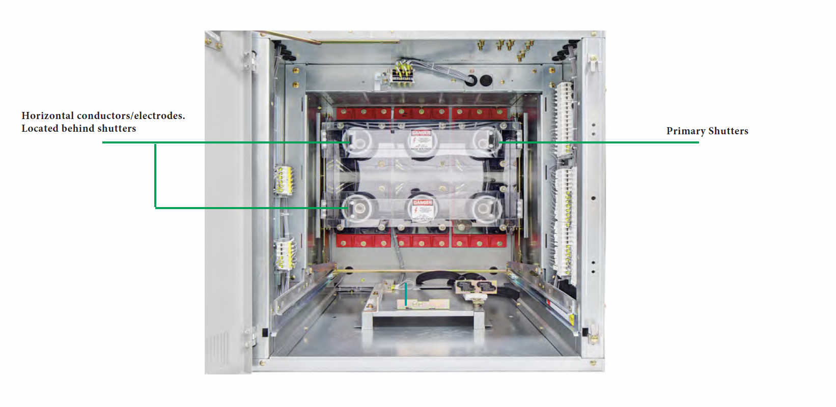
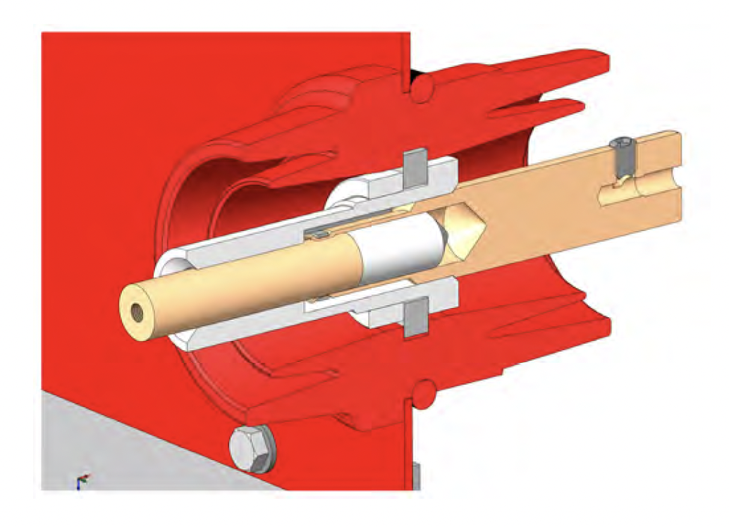
HCB HCB represents conductors that are pointed towards the enclosure opening and towards the worker. An arc initiated on the horizontal conductors will run down the bus away from the source and the plasma cloud will be directed off the ends of the conductors perpendicular to the enclosure opening, as indicated by the arrow in the diagram below. Similar to HCB, HOA represents horizontal conductors in air as opposed to a metal box or enclosure.
HOA 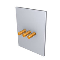
Arc Flash Reduction Devices (Maintenance Mode)A circuit breaker equipped with Maintenance Mode can improve safety by providing a simple and reliable method to reduce fault clearing time. Work locations downstream of a circuit breaker with a Maintenance Mode unit can have a significantly lower incident energy level. The energy-reducing maintenance switch is described in two sections of the 2017 National Electrical Code: article 240.87 for circuit breaker-protected circuits; and article 240.67 for fuse-protected circuits. In both cases, the function is identified as a method to reduce incident energy in circuits 1200A and larger. The requirement in the 2017 NEC 240.87 is that if the normal instantaneous protection by the circuit breaker is not able to operate at the estimated arcing current, one of several additional protection methods must be included in the circuit. The energy-reducing maintenance switch is one of these prescribed methods. An additional requirement is that the function be provided with local status indication, though the code is not clear if local means the circuit breaker, or the load at the end of the conductors protected by the circuit breaker.
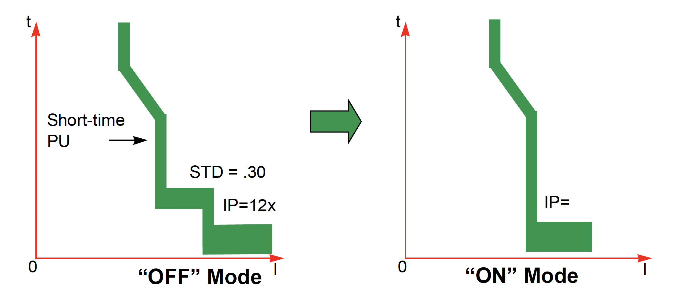
SQUARE D The ERMS function is used to reduce the Ii protection settings in order to trip as fast as possible when a fault occurs. The pre-programmed factory setting for Ii protection in ERMS mode is 2xIn. The ERMS switch can be turned “ON” to reduce circuit breaker tripping time. This sets the instantaneous pickup to a pre-programmed value; The default if not programmed = 2 x In If the ERMS instantaneous pickup is adjusted to the same or lower setting than the short-time pickup, the instantaneous function will override the short-time function and trip the circuit breaker with no intentional delay. 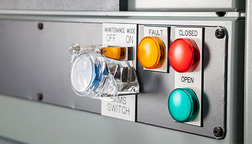
GE Reduced Energy Let-Thru (RELT) is a second Instantaneous protection element that is fully independent of all other protection elements. The user sets the threshold as needed, enables the function when required, and simply disables it when not required. Enabling or disabling the RELT function within any GE circuit breaker trip unit does not turn off or alter any other function; it enables or disables the faster instantaneous protection. EntelliGuard TU Trip UnitsRELT is an optional element. If it is not installed on your trip unit, this screen will not appear. RELT can be engaged or disengaged by dedicated remote contact or via communications. It cannot be controlled from the local keypad on the trip unit. RELT Pickup defines the threshold where the RELT Instantaneous element begins to “timeout” toward tripping, as a multiple of the Rating Plug current. RELT is adjustable between 1.5 and a breaker frame dependent maximum, similar to the INST element. RELT clearing times for the various instantaneous functions vary by circuit breaker. The RELT function clearing time is 0.042 seconds for EntelliGuard G at 60Hz and 0.05 seconds at 50Hz. Power Break versions of the EntelliGuard TU trip unit clear in 0.05 seconds. For Power Break II, AKR, and WavePro circuit breakers the clearing times are 0.05 and 0.058 seconds for RELT and selective instantaneous respectively at 60 Hz. General Electric RELT Guides
EATON ARMS uses a separate electronic trip circuit providing faster signal processing and interruption times than the standard ‘instantaneous’ protection. When enabled, the trip unit will trip the breaker with no intentional delay whenever the configured pickup level is exceeded. When enabled, the Maintenance Mode function operates regardless of the instantaneous settings. Clearing time of the associated circuit breaker is reduced below the level of the breaker’s standard instantaneous response. 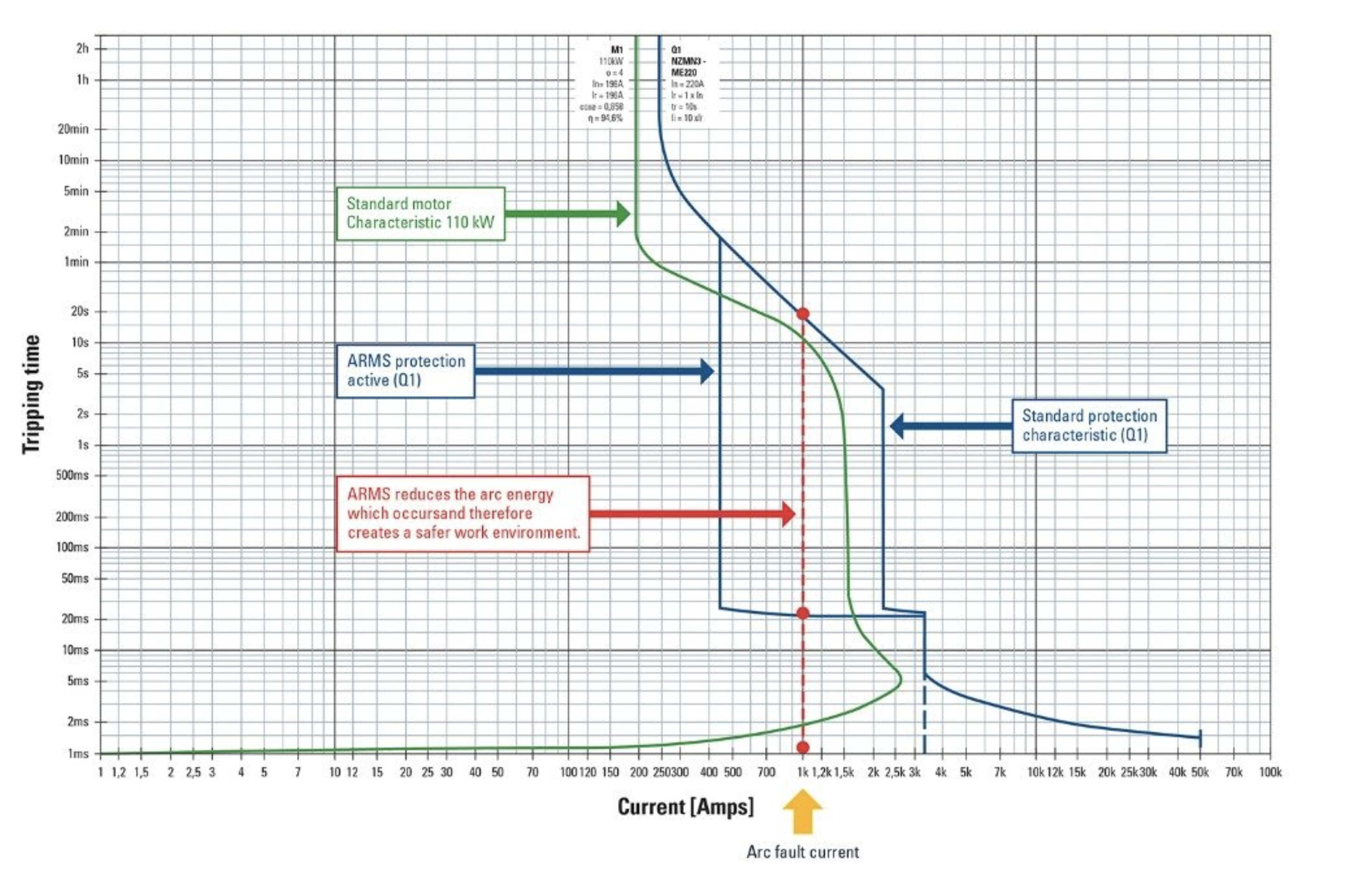
An activated ARMS function provides for faster triggering in case of overload. In the example above, the fault current is 1000A. The ARMS maintenance mode will cause the breaker to trip in 20ms instead of 20s.
SIEMENS Sentron Sensitrip IVWhen the Dynamic Arc-Flash Sentry mode is activated, the Instantaneous pickup setting (Ii) is reduced to the lessor of [2 x In] and the [Ii dial setting]. Reference Material
|
|


| Arc Flash Label Data | ||||||||||||||||||||||||||||
|---|---|---|---|---|---|---|---|---|---|---|---|---|---|---|---|---|---|---|---|---|---|---|---|---|---|---|---|---|
|
||||||||||||||||||||||||||||
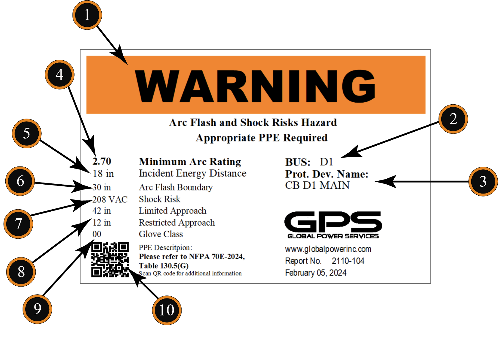
NFPA 70E-2024 Label RequirementsNEC 70E-2024 130.5
(H) Equipment Labeling. 1. Nominal system voltage 2. Arc flash boundary 3. At least one of the following: a. Available incident energy at the corresponding work distance, or the arc flash PPE category in Table 130.7(C)(15)(a) or Table 130.7(C)(15)(b) for the equipment, but not both b. Minimum arc rating of clothing c. Site-specific PPE Incident EnergyIs the amount of thermal energy impressed on a surface, a certain distance from the source, generated during an electric arc event. It is based on the available fault current, working distance, and the clearing time of the fault. The unit of measurement for incident energy is calories per centimeter squared. To give you an idea of what this means, 1 cal/cm2 is equivalent to the energy produced from a lighter in one second. Arc Flash BoundaryIs the shortest distance from the arc at which a person could receive permanent injury or the onset of a second degree burn (1.2 cal/cm2), if not wearing properly rated PPE. *A third degree burn begins at 10.7 cal/cm2. 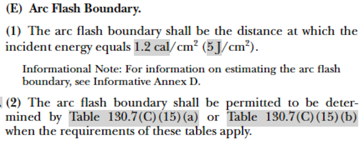
NFPA 70E Article 130.5(E) 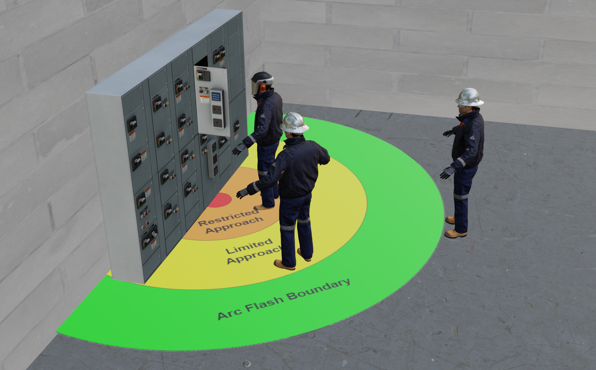
Arc Flash Boundary Limited ApproachThe outer boundary at which a worker may be exposed to a shock hazard, the limited approach boundary, refers to the“stay back” distance for non-qualified workers. Qualified workers may cross this boundary after shock and arc flash risk assessments are performed with appropriate PPE if needed. Appropriate PPE should be worn by qualified workers in the limited space (space between the limited approach boundary and the restricted boundary). 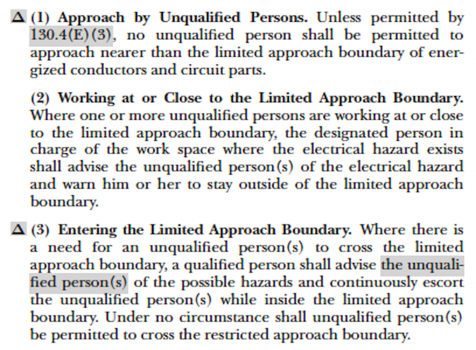
NFPA 70E Article 130.4(E) *The “prohibited approach” boundary was removed in the 2015 NFPA 70E edition.
Limited Approach Boundary Restricted Approach Boundary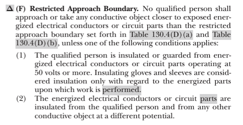
The area closest to the live or exposed equipment is the restricted approach boundary, in which only qualified workers with proper training may enter. Energized WorkIf the equipment is still energized and justified energized work needs to be completed, an energized electrical work permit may be needed, and documentation is required. This includes a specific plan of action, a list of protective steps to be taken, and supervisory approval.
Restricted Approach Boundary 
PPE SelectionThe National Fire Protection Association (NFPA) details how to comply with the Occupational Safety and Health Administration's (OSHA) regulation, 29 CFR 1910.333(a) , through the NFPA 70E, standard. NFPA 70E, ARTICLE 130.5 says an arc flash assessment must be completed to determine if an arc flash hazard exists.
NFPA 70E-2024 Article 103.5
Expand / Collapse
NEC 70E-2024 130.5 Arc Flash Risk Assessment
(A) General
NFPA 70E-2024 Article 103.5(F)
Expand / Collapse
This article provides the following two options for selecting PPE. The first method, Incident Energy Analysis, is the one that applies to Arc FLash Analysis Reports. Article 130.5(F) states: NEC 70E-2024 130.5(F)
(F) Arc Flash PPE
Either, but not both, methods shall be permitted to be used on the same piece of equipment. The results of an Incident Energy Analysis to specify an arc flash PPE category in Table 130.7(C)(15)(c) shall not be permitted. The first method, Incident Energy Analysis, is the method that applies to Arc flash Studies performed by GPS. Unlike the incident energy analysis method, the PPE category method does not involve calculations. This method uses tables to estimate the risk based on maximum available fault currents, clearing times of overcurrent protective devices such as breakers and fuses, and working distances. If known, the fault currents at the equipment and clearing times are cross-referenced with the tables to determine the arc flash PPE category and arc flash boundary. Using this method, the arc flash labels will identify the PPE Category rather than the incident energy. NFPA 70E Table 130.5(G) should not be used with this method.
NFPA 70E-2024 Article 130.5(G)
Expand / Collapse
NEC 70E-2024 130.5(G)
(G) Incident energy analysis Method The incident energy analysis shall take int consideration the characteristics of the overcurrent protective device and its fault clearing time, including its condition of maintenance. The incident energy analysis shall be updated when changes occur in the electrical distribution system that could affect the results of the analysis. The incident energy analysis shall also be reviewed for accuracy at intervals not to exceed 5 years. Table 130.5(G) identifies the arc-rated clothing and other PPE requirements of Article 130 and shall be permitted to be used with the incident energy analysis method of selecting arc flash PPE.
NFPA 70E-2024 Table 130.5(G)
Expand / Collapse
"Table 130.5(G) identifies arc-rated clothing and other PPE requirements and shall be permitted to be used with the Incident Energy Analysis method of selecting arc flash PPE" 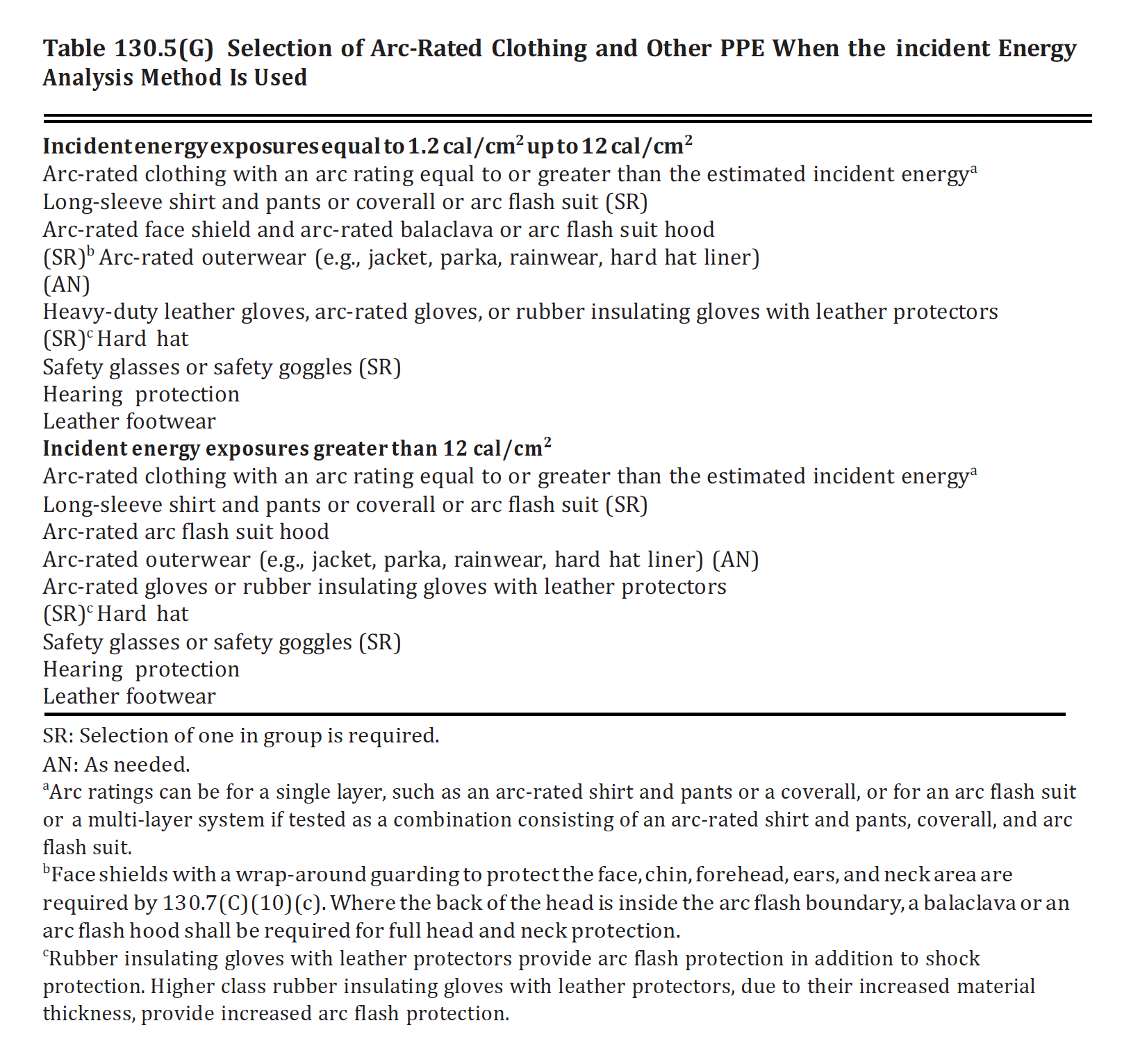
TABLE 103.5(G) DescriptionSelection of Arc-Rated Clothing and other PPE When the Incident Energy Analysis Method is UsedIncident Energy Exposures equal to 1.2 cal/cm2 up to 12 cal/cm2TABLE 103.5(G) DescriptionSelection of Arc-Rated Clothing and other PPE When the Incident Energy Analysis Method is UsedIncident Energy Exposures greater than 12 cal/cm2Frequently Asked QuestionsQuestion 1:Should I put Maintenance Mode Incident Energy Values on arc flash labels?Answer:Over the past decade, electrical equipment manufacturers have introduced products featuring a "Maintenance Mode." This setting allows users to temporarily adjust the trip time of relays or low-voltage circuit breaker trip units, enabling them to respond more quickly and reduce arc flash hazards on the protected bus. Users can activate this mode via a switch on the front panel or an electrical control signal sent to the back of the panel. This method of hazard reduction is preferred over simply increasing the level of personal protective equipment (PPE) for workers exposed to higher energy levels. Since it is considered a form of hot work, the relevant information should not appear on a label. Instead, the maintenance procedure, appropriate PPE, and instructions for using the Maintenance Mode feature should be officially approved and included in the Hot Work Permit. |
||||||||||||||||||||||||||||