| Power Systems Basics | |
|---|---|
Alternating WaveformsVoltageThe voltage v(t) in an AC circuit can be described by the equation: \( \Large v(t) = \Large V_{max} \sin(\omega t+\phi_{v} ) \) CurrentThe voltage v(t) in an AC circuit can be described by the equation: \( \Large i(t) = \Large I_{max} \sin(\omega t+ \phi_{i} ) \)
Where: Inductors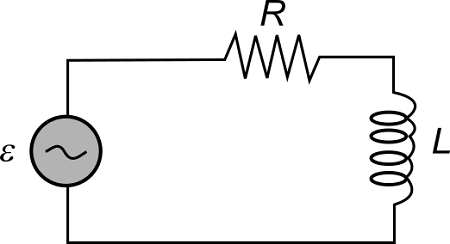
What is an Inductor? DC Inductors
Behavior in DC Circuit
Initial Phase (t=0):
Transient Phase:
Steady State: Response over time
Behavior in DC Circuit \( \Large I(t) = \Large \frac{V}{R} ( 1-e^{-\frac{R}{L}t}) \) VoltageThe voltage v(t) across an inductor: \( \Large V(t)_{L} = \Large V_{\normalsize source} \: e^{-t/\tau} \) CurrentThe current I(t) through an inductor: \( \Large I(t)_{L} = \Large I_{\normalsize source} \: e^{-t/\tau} \) InductanceCapacitive Resistance magnitude equation, in ohms: \( \Large X_{C}= \Large 2 \pi fL \)
Where: CapacitanceCapacitance\( \Large Q = CV \) \( \Large C = \frac{\varepsilon A}{d} \) VoltageThe voltage v(t) across a capacitor: \( \Large V(t)_{c} = \Large V(0)_{c} + \frac{1}{C} \int_{0}^{t} i(\tau)_{c} \; d\tau \) CurrentThe current I(t) through a capacitor: \( \Large i(t)_{c}= C(\frac{dv_{c} }{dt}) \) ImpedanceIdeal Capacitance, in Farads (F): \( \Large X_{C}= \Large \frac{1}{\Large 2 \pi fC } \) Capacitance
\(\Large f\) is the frequency in hertz
Where: Capacitance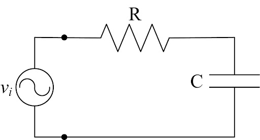
VoltageThe voltage v(t) across an inductor: \( \Large V(t)_{L} = \Large V_{\normalsize source} \: e^{-t/\tau} \) CurrentThe current I(t) through an inductor: \( \Large I(t)_{L} = \Large I_{\normalsize source} \: e^{-t/\tau} \) InductanceCapacitive Resistance magnitude equation, in ohms: \( \Large X_{C}= \Large \frac{1}{\Large 2 \pi fC } \)
Where: Impedance
Impedance (Z) is a comprehensive measure that combines resistance (R) and reactance (X), accounting for the total opposition a circuit presents to alternating current. It's expressed in ohms (Ω) and plays a crucial role in analyzing AC circuits, affecting voltage, current, and power factor. \( \Large Z = \huge \frac{V}{I} \) \( \Large Z = \Large R \times jX \) \( \Large X = \Large X_{L} - X_{C} \) \( \Large X_{L}= \Large 2 \pi fL \) \( \Large X_{C}= \Large \frac{1}{\Large 2 \pi fC } \)
Where:
Complex powerComplex power in electrical engineering refers to the power flow in AC circuits, encompassing both real and reactive power components, which represent the actual power consumed by loads and the power stored in the system, respectively. It's crucial in understanding power system operations, including generation, transmission, and distribution, as well as in the design and analysis of AC electrical systems. \( \Large S = \Large P \times jQ \) \( \large P = \large VI \cos(\varphi) = V^{2}I = I^{2}R \) Real power P is the capacity of the circuit for performing work in a particular time. It is given by: \( \large Q = \large VI \sin(\varphi)\) Reactive power Q represents the energy that oscillates between the source and the reactive components (inductors and capacitors) in the system. It is given by:
Where: 3 Phase Power\( \Large S = \Large P \times jQ \) \( \Large S = \Large 3V_{p} I_{p}^{*}\) \( \large \hspace{1em}\: = \sqrt{3} V_{L} I_{L} ( \cos(\theta_{P}) +j \sin(\theta_{P} ) \) \( \large |S| = \large 3V_{P}^{2} I_{P} = \sqrt{3} V_{L}^{2} I_{L}\) DELTA \( \Large S = \Large 3\frac{ V_{P}^{2}}{ Z_{DELTA}^{*}} \) WYE \( \Large S = \Large \frac{ V_{P}^{2}}{ Z_{WYE}^{*}}\) Power Factor PowerPower factor (PF) is a critical measurement in AC electrical systems, representing the ratio of real power flowing to the load to the apparent power in the circuit. It is a dimensionless number ranging between -1 and 1, and it's a key indicator of electrical efficiency. Real power P is the capacity of the circuit for performing work in a particular time. It is given by: \( \large PF = \large \cos(\varphi)\) where \(\Large \varphi\) is the phase angle between the voltage and the current waveforms. A power factor of 1 (or -1) means that all the power is real power, which is ideal because it means all the power supplied is being used for useful work. A power factor less than 1 indicates the presence of reactive power in the system, which does not perform work but creates additional load on the electricity supply. There are two types of power factors: leading and lagging. A lagging power factor occurs in inductive loads, such as motors and transformers, where the current lags behind the voltage. A leading power factor occurs in capacitive loads, where the current leads the voltage. Improving the power factor in a system can lead to several benefits, including reduced transmission losses, improved voltage levels, and lower electricity costs. Methods to improve power factor include:
In the context of motor starting and electrical load monitoring, as discussed in the documents, power factor plays a crucial role. During motor starting, the inrush current can cause a significant drop in power factor, leading to higher demands on the electrical supply and potential voltage drops. Proper sizing of start-up equipment and protective devices is necessary to manage the effects of low power factor during start-up phases. Additionally, in electrical load monitoring, understanding and correcting power factor issues is essential for ensuring system reliability, optimizing performance, and reducing operational costs. Monitoring equipment not only tracks current and voltage but can also measure power factor to identify inefficiencies and areas for improvement in the electrical system. |
|
| Switchgear | |
|---|---|
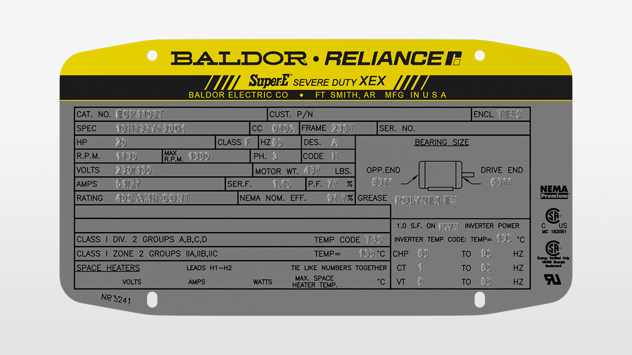
Name Plate DataMotor nameplate terminology refers to the standardized information provided on the nameplate of an electric motor. Here's an overview of common terms and data typically found on a motor nameplate:
Medium Voltage Switchgear
Voltage Level:
Components:
Applications:
Example: 
Switch Board Structure
Switchboard Structure
Busbars:
Insulators:
Surge Arresters:
Connections:
Grounding Switches:
Current Transformers (CTs):
Voltage Transformers (VTs):
Thermostats: 
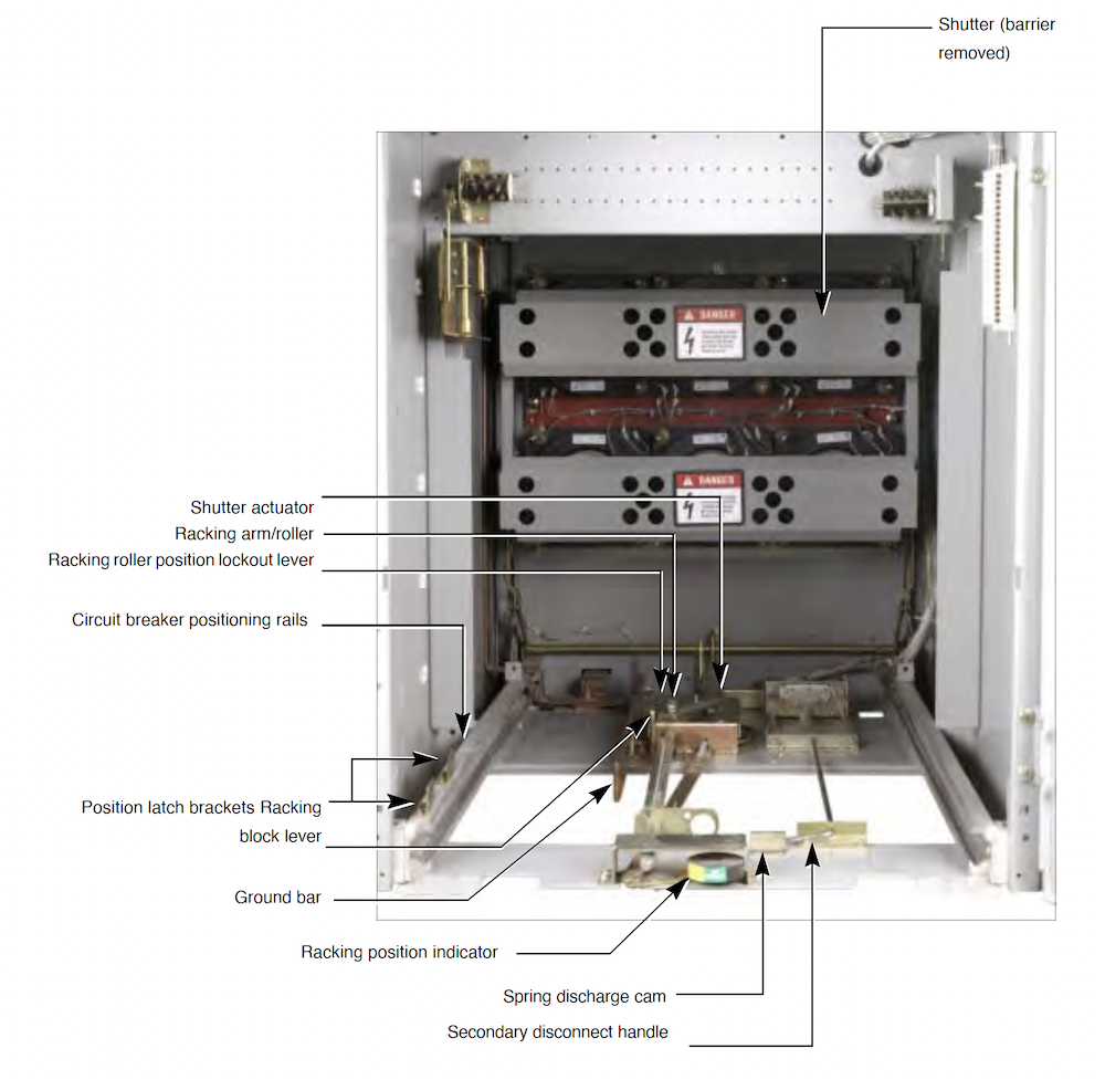
Breaker Compartment
Operating Mechanism: 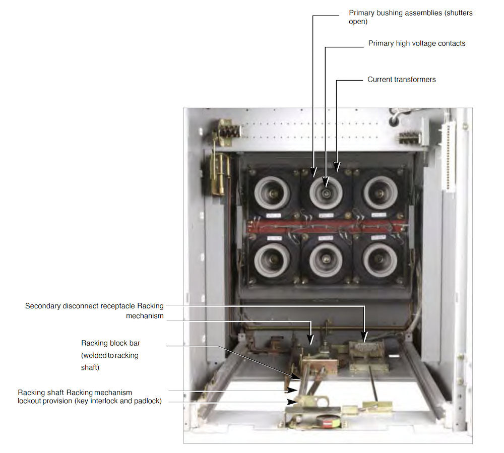
Breaker Wiring
Operating Mechanism: 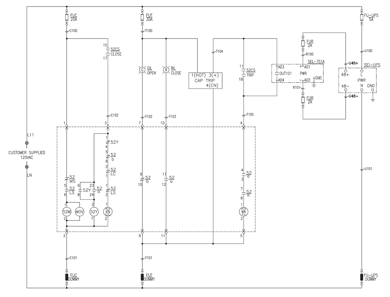
Control Relays:
Protective Relays
Protective Relays:
Electromechanical Relays:
Static Relays:
Digital (Microprocessor-Based) Relays: 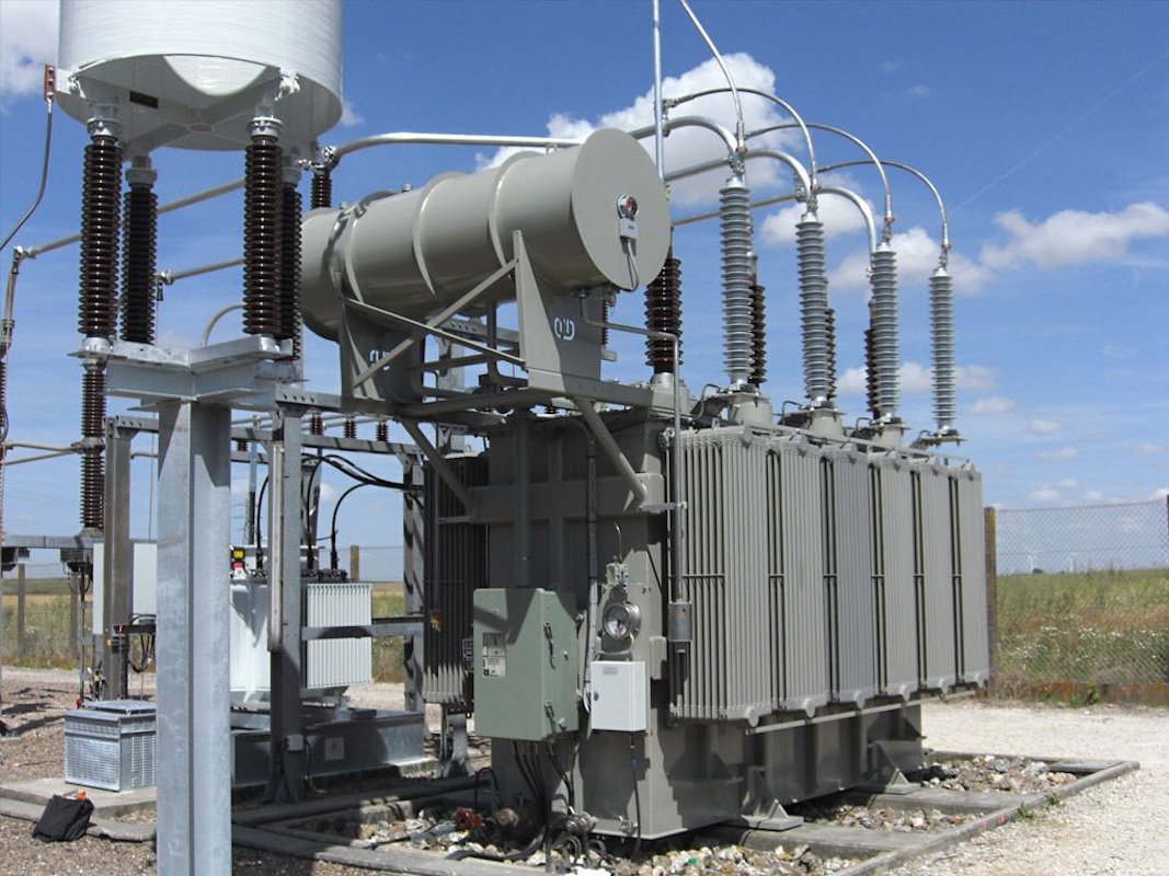
Control Relays:
Control Relays:
Metering Devices:
Metering Devices:
Wiring:
Wiring:
Terminal Blocks:
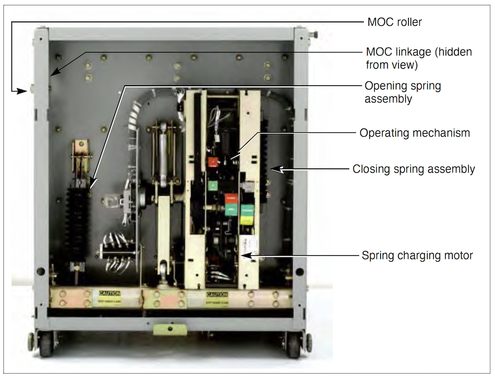
Circuit Breaker
Vacuum Breaker
Circuit Breaker: 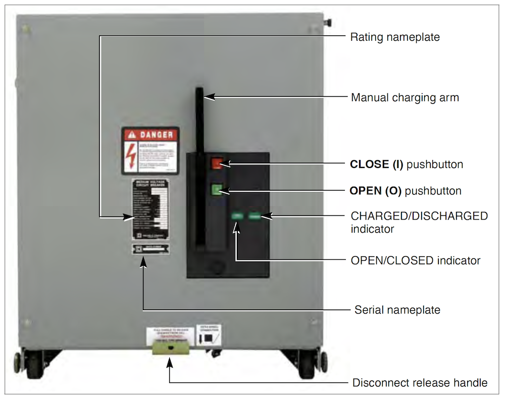
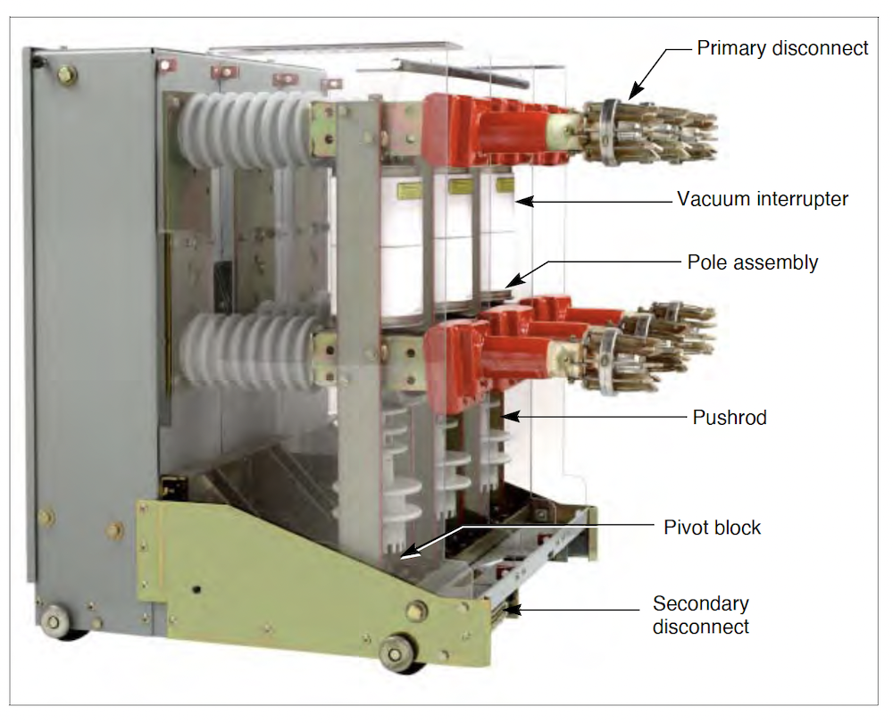
Aux Contacts
Operating Mechanism: 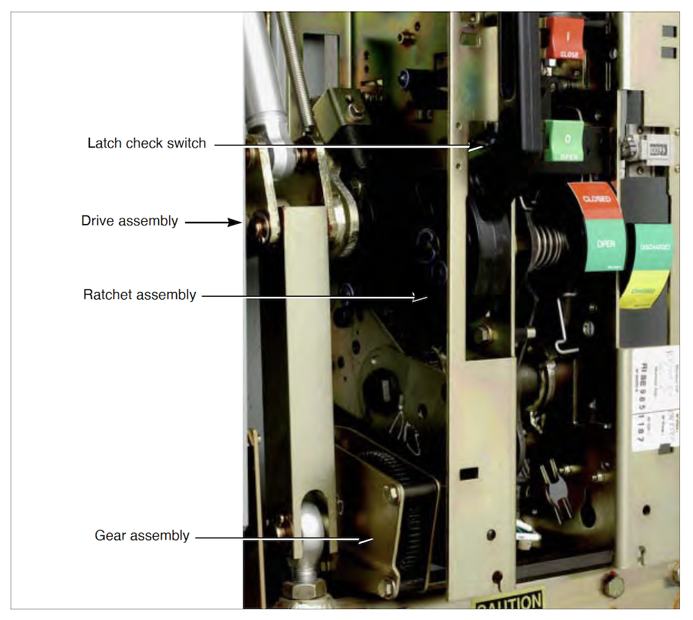
Spring Charging Motor:
Latch Check Switch: 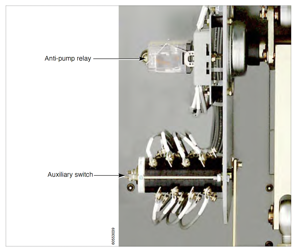
Auxiliary Switch:
The auxiliary switch functions as follows:
Anti-Pump Relay: OPEN (O) and CLOSED (|) in the event that a trip signal is also present. The anti-pump relay performs this function by allowing the closing coil to activate only if: • the circuit is energized, • the closing springs are fully charged, and • the spring charging motor is de-energized. The anti-pump relay activates when the close circuit is energized while the circuit breaker is closed. If the close circuit is energized continuously, the anti-pump relay will remain in the energized position after the 52/a auxiliary contact closes during the closing operation. When the anti-pump relay is energized, a pair of its normally-closed contacts, in series with the close coil, will open to ensure that the close coil cannot be energized. The close coil activates only when the close circuit is de-energized (de-energizing the anti-pump relay), then energized again.
Trip and Close Coils: 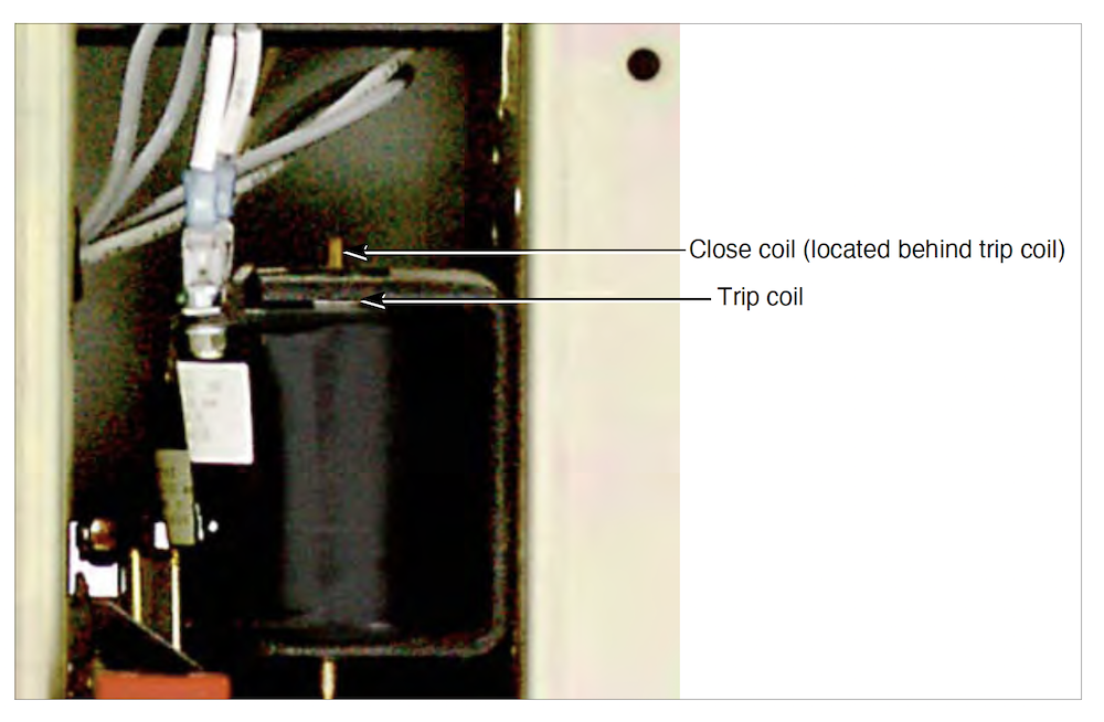
trip and close coils: 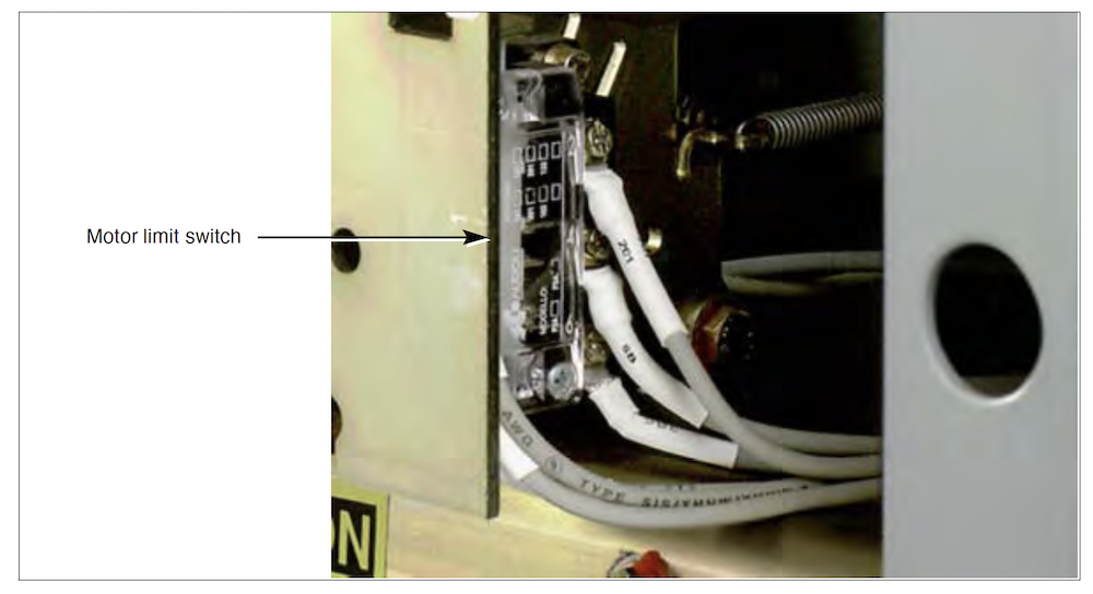
Motor Limit Switch: Auxilary Devices:
Current Transformers:
Protective Relays:
Current Transformers (CTs):
Voltage transfromers
Voltage Transformers (VTs):
Wiring:
Wiring:
Wiring and Controls
Breaker Wiring
Operating Mechanism: |
|
| Circuit Breakers, Low Voltage < 600V | |
|---|---|
|
|
|
What is the purpose of a circuit breaker?Circuit breakers are protective devices, which perform two primary functions:
Similar to switch, circuit breakers are the primary way to energize and de-energize the circuit. Specialized circuit breakers can also be opened or closed remotely. Overloading of electrical equipment, such as cables, can deteriorate insulation due to thermal stress cause by heat. As current increases past the cables design rating, insulation will begin to deteriorate. Over an extended period of time, leakage current will increase, eventually causing it to fail. 
Name Plate Rating Definitions
Continuous current is the maximum value of steady state amperes that the CB contacts and internal conductors are designed to carry. Rated voltage is the maximum operating voltage for which the circuit breaker is designed. Voltage ratings are given in terms of threephase linetoline voltage. Rated interrupting current is the maximum current that the CB is designed to interrupt at the time the contacts part. Rated voltage is the maximum operating voltage for which the circuit breaker is designed. Voltage ratings are given in terms of three-phase line-to-line voltage. The short time current rating is the maximum amount of current in amperes which the CB contacts and internal conductors can carry, without damage, for a short time period (typically, three seconds). This rating also accounts for permanent stress to insulation, heat, and electromagnetic effects. 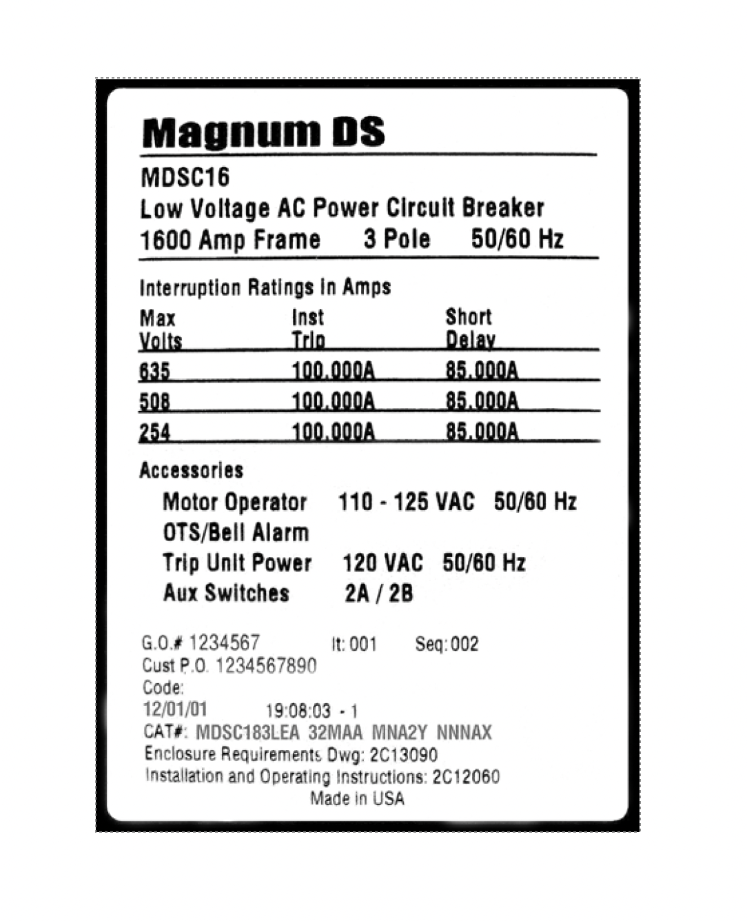
Molded Case Breakers
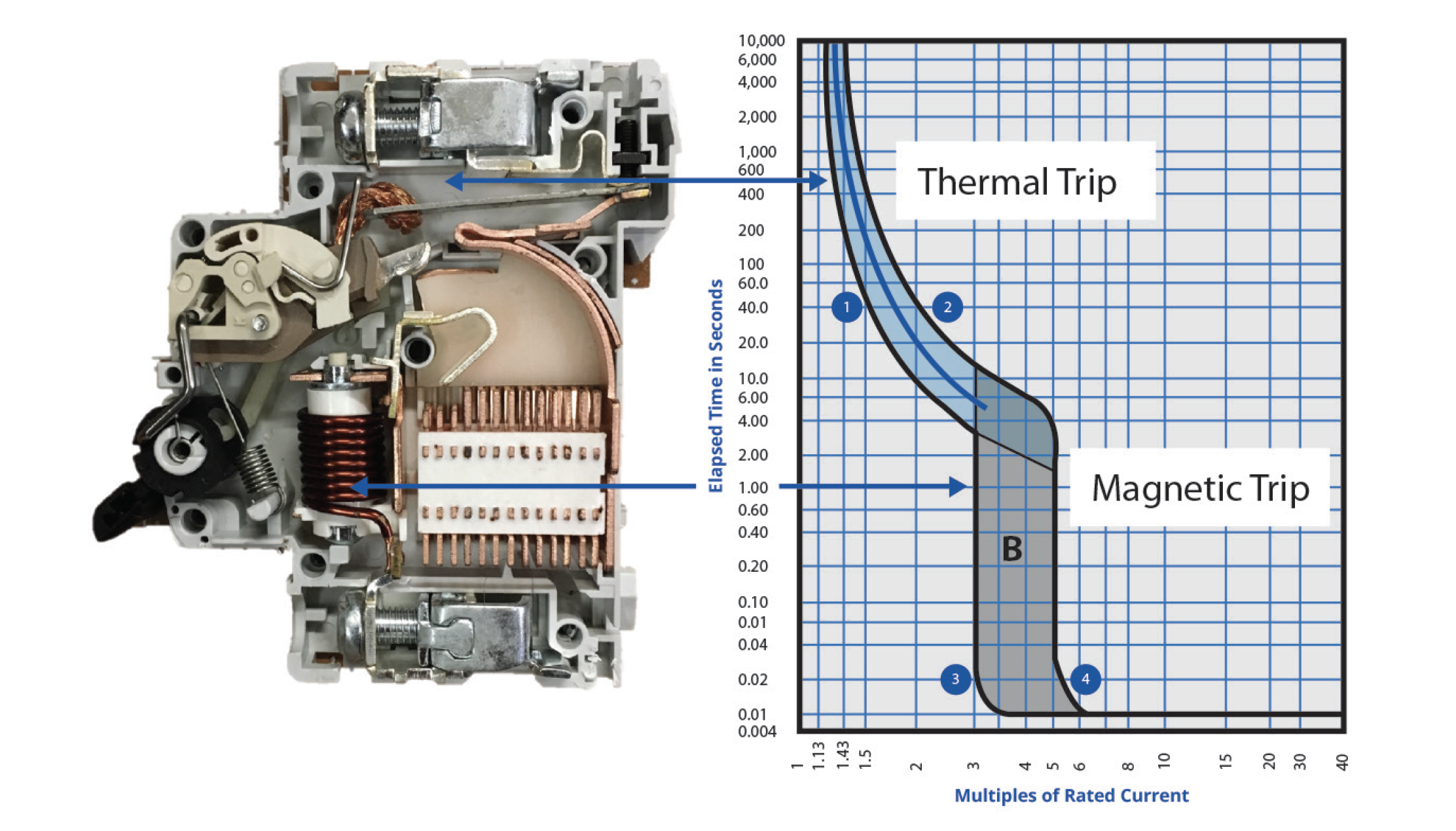
Molded Case Circuit Breakers (MCCB)MCCB are the most widely used type of circuit breakers. They are available in a wide range of ratings and are generally used for low-current, low-energy power circuits. They can be found in residential, commercial, and industrial facilities. MCCB have two protective elements built in to them.
provides an inverse time–current characteristics for over-current protection provides short circuit current protection 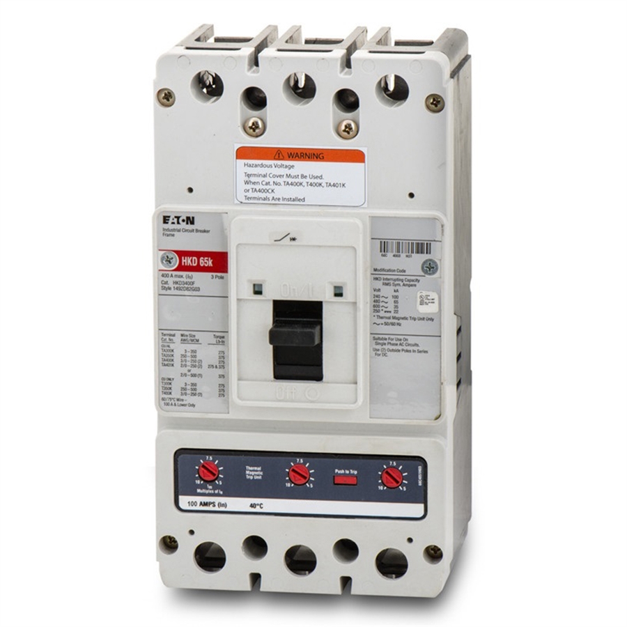
Insulated Case Breakers
Insulated-case circuit breakersInsulated-case circuit breakers are a type of molded-case breaker constructed with glass reinforced insulating material for increased dielectric strength. These breakers can have Electromechanical trip units which was discussed above, or an Electronic trip units offer capabilities such as programming monitoring diagnostics communications system coordination and testing that are not available on thermal magnetic trip units. 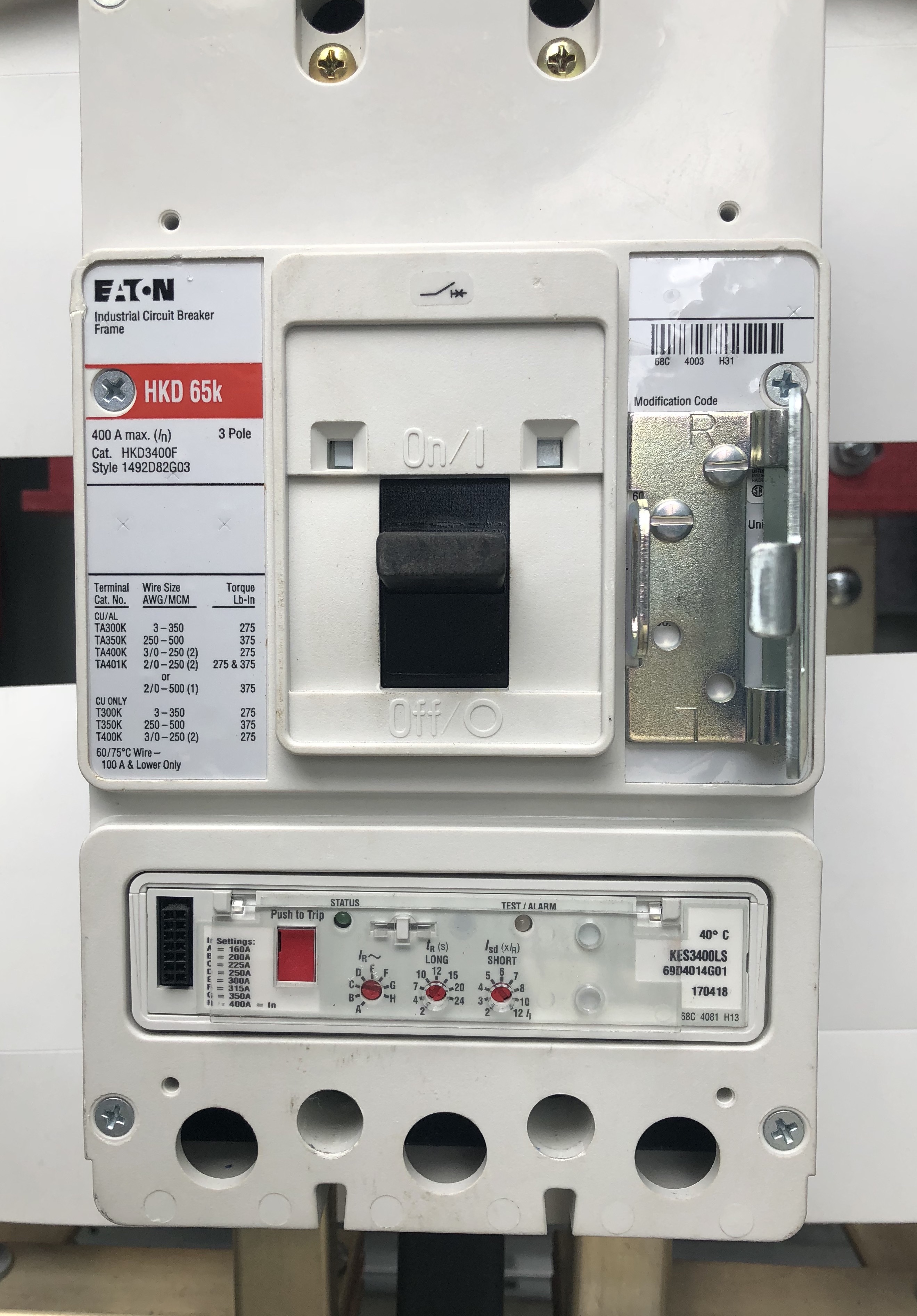
Draw-Out Power Circuit BreakersGenerally, these breakers have draw-out features whereby individual breakers can be put into test and fully de-energized position for testing and maintenance purposes. Generally, these breakers have draw-out features whereby individual breakers can be put into test and fully de-energized position for testing and maintenance purposes. 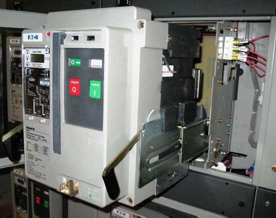
Motor Circuit Protection (MCP)
Motor Circuit Protector (MCP)Magnetic-trip-only breakers have no thermal element. Such breakers are principally only used for isolating the circuit and short-circuit protection.
Molded-case breakers with magnetic only trips
find their application in
motor circuit protection. MCP's can be found
inside They are typically placed inside a cubical or enclosure, along with motor control elements and a motor over-current device; commonly knows as a heater. 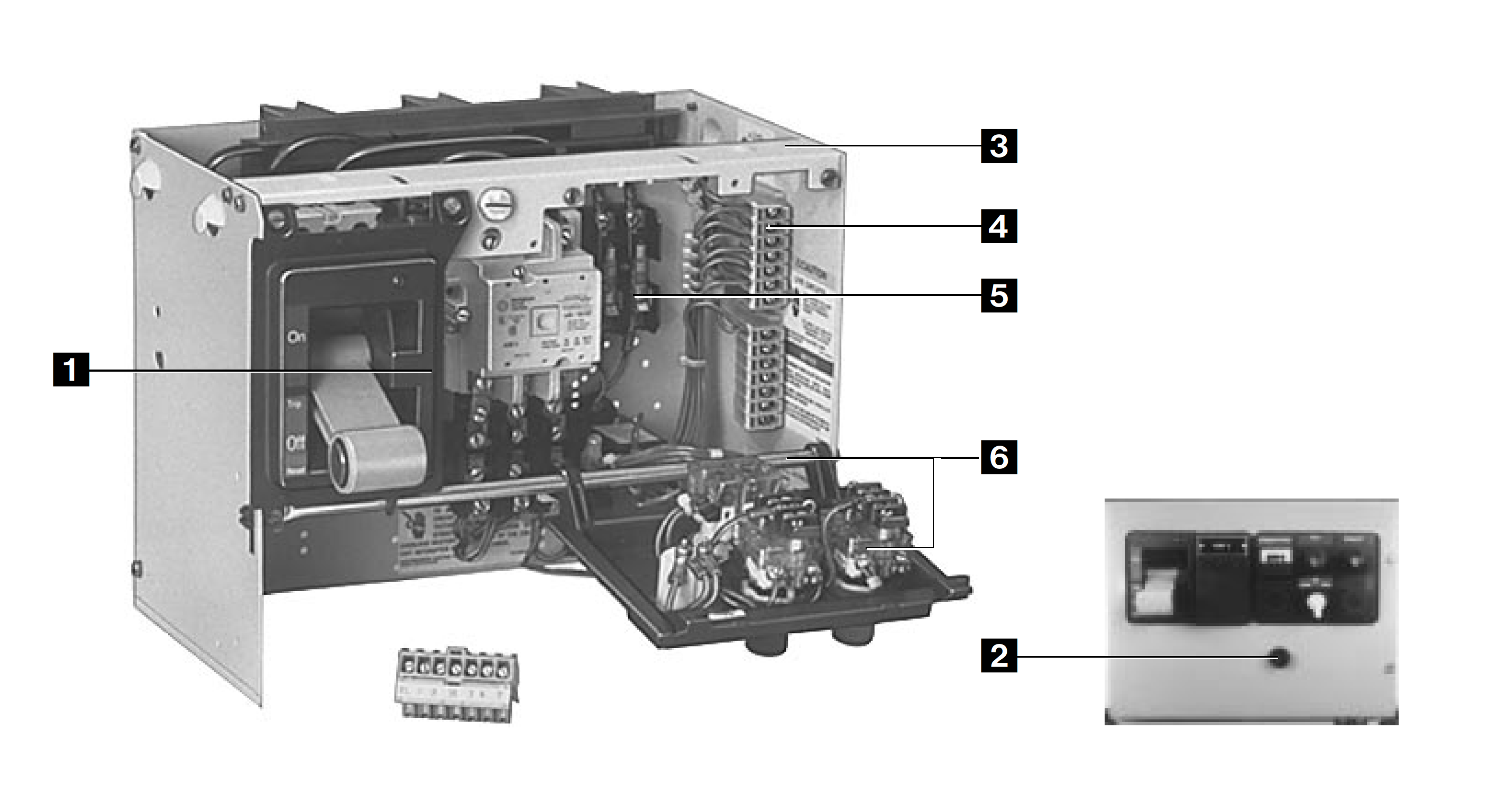
EatonTime Current Curves (TCC)Manuals and DocsGETime Current Curves (TCC)
Manuals and Docs |
|
| Circuit Breakers, High Volatge > 600V | |
|---|---|
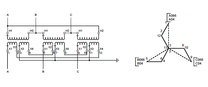
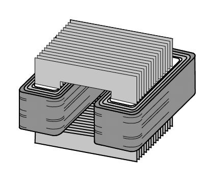
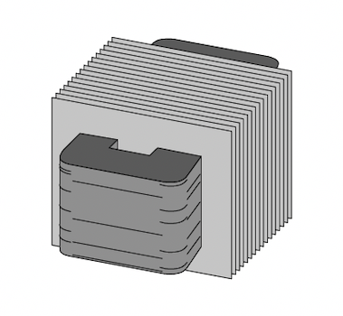
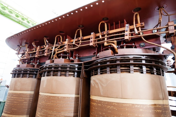
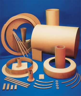
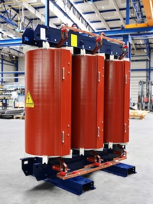
Transformer WindingsThe purpose of transformer winding configurations or connections is to keep the correct phase angle displacement between different voltage levels, and to provide a return path for ground fault current. This section will use line drawings and explanations for the uses, advantages and schematic identification of each of the connections and their various combinations. Winding Configurations
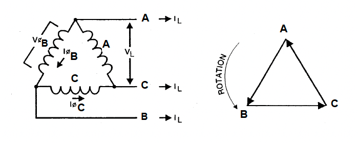
Delta Connection:
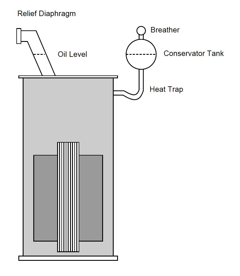
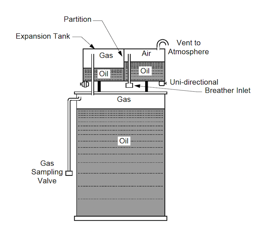
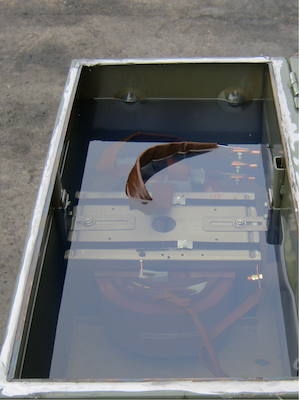
Sealed Tanks
Purpose
Description:
Specific Application:
Pros:
Cons:
Sealed Transformer Tank
Air-Magnetic Circuit Breakers
Description
Purpose:
Specific Application:
Voltage Levels: 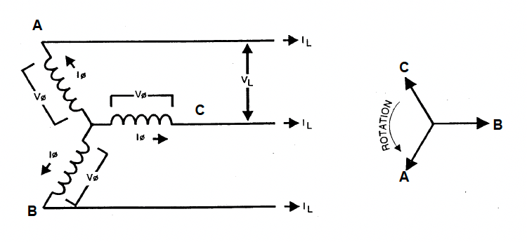
Voltage-Current Relationship \( \Large V_{L} = \sqrt{3} \times V_{\phi}\) \( \Large I_{L} = I_{\phi}\)
Advantages Wye-Wye Connection
Advantages
Disadvantage 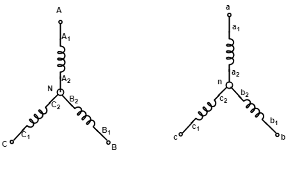
Zig Zag
Zig-Zag Connection
Description
Advantages
\( \Large V_{L} = \sqrt{3} \times V_{\phi}\) \( \Large I_{L} = I_{\phi}\) Name Plate Data
Power Rating:
Rated Voltages:
Impedance:
Vector Configurations:
Taps:
BIL: General:
Core and Windings:
Temperature Rise:
Cooling:
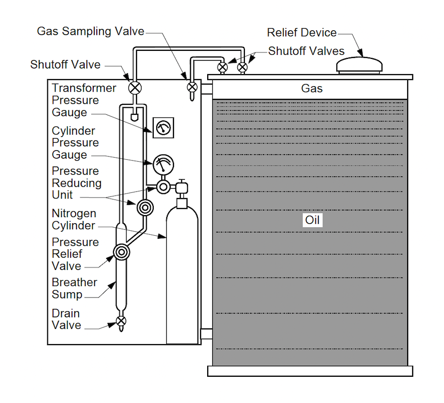
Type of Oil:
Oil Volume:
PCB Content: |
|
| Electric Motors | ||||||||||||||||||||||||||||||||||||||||||||||||||||||||||||||||||||||||||||
|---|---|---|---|---|---|---|---|---|---|---|---|---|---|---|---|---|---|---|---|---|---|---|---|---|---|---|---|---|---|---|---|---|---|---|---|---|---|---|---|---|---|---|---|---|---|---|---|---|---|---|---|---|---|---|---|---|---|---|---|---|---|---|---|---|---|---|---|---|---|---|---|---|---|---|---|---|
|
||||||||||||||||||||||||||||||||||||||||||||||||||||||||||||||||||||||||||||
Electric Motor Current calculatorHorsepower: Three Phase\( \textbf{FLA} = \Large \frac{ \textbf{HP} \times 746}{\sqrt{3} \times V \times \cos \phi \times \eta} \) Single Phase\( \textbf{FLA} = \Large \frac{ \textbf{HP} \times 746}{V \times \cos \phi \times \eta} \) \( \textbf{1 HP} = 746 \thinspace \textbf{Watts} \) \( \textbf{Power Factor} = \Large \cos \phi \) \( \textbf{Efficiency} = \Large \eta \) Watts: Three Phase\( \textbf{FLA} = \Large \frac{ \textbf{KW} \times 1000}{\sqrt{3} \times V \times \cos \phi \times \eta} \) Single Phase\( \textbf{FLA} = \Large \frac{ \textbf{KW} \times 1000}{ V \times \cos \phi \times \eta} \) \( \textbf{1 Watt} = 0.00134102 \thinspace \textbf{HP} \) \( \textbf{Power Factor} = \Large \cos \phi \) \( \textbf{Efficiency} = \Large \eta \) Name Plate DataMotor nameplate terminology refers to the standardized information provided on the nameplate of an electric motor. Here's an overview of common terms and data typically found on a motor nameplate:
RATED POWER (HORSEPOWER OR KILOWATTS) AC motors used in North America are generally rated in horsepower. Equipment manufactured in Europe is generally rated in kilowatts (KW). Horsepower can be converted to kilowatts using the following formula: \( \textbf{1 Watt} = 0.001341 \thinspace \textbf{HP} \) Kilowatts can be converted to horsepower using this formula: \( \textbf{1 HP} = 746 \thinspace \textbf{Watts} \)
TORQUE: \( \textbf{HP} =\Large \frac{Torque \times rpm}{Constant} \)
If Torque is given in ft-lbs, the constant is 5,252
RATED VOLTAGE Since the voltage from the power supply can fluctuate over time due to changing load conditions in the power system, motors need to handle some voltage variation. Standard induction motors are typically designed to tolerate voltage variations of plus or minus 10%. For example, a motor with a nameplate voltage rating of 230 volts can operate satisfactorily with a voltage range between 207 and 253 volts, though performance might not be ideal at these extremes. Manufacturers sometimes list multiple voltages on a motor’s nameplate. For instance, a motor designed for 230 and 460 volts (230/460 V) might also be capable of operating on 208 volts. In such cases, the nameplate might read 208-230/460 V. However, at 208 volts, the motor will likely experience reduced performance compared to its optimal operation at 230 or 460 volts.
LOCK ROTOR CURRENT: To simplify understanding inrush characteristics, motors are grouped by code letters that represent the range of inrush currents in kilovolt-amperes (kVA). These code letters indicate the inrush current for both low and high voltage on dual-voltage motors. Electricians use this information to properly size the motor starter. The following is a listing of the code letter designations:
A chart with locked-rotor code letters defines the inrush current needed when starting a motor. This chart shows the locked-rotor kVA per horsepower (HP) and indicates that inrush current per HP increases with each letter. Replacing a motor with one that has a higher locked-rotor code may require upgrading upstream electrical equipment to handle the higher inrush currents.
FULL LOAD RPM: An induction motor's speed is always less than synchronous speed and it drops off as load increases. For example, for 1800 rpm synchronous speed, an induction motor might have a fullload speed of 1750 rpm. On standard induction motors, the full load speed, or actual speed, will normally be between 96 and 99% of synchronous speed. This is also known as slip. Multi-speed shaded pole and PSC motors show maximum speed first, followed by total number of speeds (i.e., 3000/3-Spd). Multi-speed split phase and capacitor-start motors have maximum speed shown first, followed by second speed (i.e., 1725/1140). RPM rating for a gear motor represents output shaft speed. "High" efficiency motors have usually higher speed ratings than comparable sized standard efficiency motors. This higher operating speed can actually increase power consumption in centrifugal loads (e.g., pumps and fans). For centrifugal loads, power varies as the cube of speed. Thus, a 1% increase in speed will result in a 3% increase in power (1.013= 1.03).
SYNCHRONOUS SPEED (RPM): \( \textbf{S} = \Large \frac{120 \times Freq}{Poles} \)
\( \textbf{S}= \text{Speed in RPMS} \)
FULL LOAD AMPS (FLA):
SERVICE FACTOR: For example, the standard SF for open drip-proof (ODP) motors is 1.15. This means that a 10-horsepower (hp) motor with a 1.15 SF can temporarily provide up to 11.5 hp when needed. Some smaller motors, known as fractional horsepower motors, have even higher service factors, such as 1.25, 1.35, or even 1.50, allowing them to handle more overload for short periods.
ENCLOSURE TYPE:
Open Drip Proof (ODP):
Totally Enclosed Fan Cooled (TEFC):
Totally Enclosed Non-Ventilated (TENV):
Totally Enclosed Air Over (TEAO):
Totally Enclosed Wash down (TEWD):
Totally enclosed, hostile and severe environment motors:
Explosion-proof enclosures (EXPL):
Hazardous Location (HAZ):
NEMA DESIGN LETTER:
NEMA Design A motors
NEMA Design B motors
NEMA Design C motors
NEMA Design D motors
RATED TEMPERATURE RISE OR INSULATION CLASS:
This standard 20,000 hour life temperature class is based on ambient plus the heat created within the motor during operation. Please keep in mind that motors are designed to withstand some very high temperatures. As an example, Class B is rated at 130°C, which is 266°F, or 54 degrees above the boiling point of water. Motors have been designed to withstand this type of heat. Insulating materials prevent metal to metal contact or interaction of phase to phase shorts. This is also known as dielectric strength. It limits the effects of voltage variations. Insulation System Classes are as follows: 
Insulation classes perform better in an ascending alphabetical order. For example, class F insulation has a longer nominal life at a given operating temperature than class A, or for a given life it can survive higher temperatures.
FRAME SIZE Standardized frames for integral horsepower induction motors range from 143T to 445T, covering most motors from one to two hundred horsepower. The numbers in the frame size have specific meanings related to the motor's physical size. The first two digits indicate the motor shaft height, while the remaining digit(s) relate to the motor's length. To calculate the shaft height in inches (the "D" dimension) for horizontal motors, divide the first two digits of the frame size by four. This rule applies to all foot-mounted NEMA frame motors within the 143T to 445T range. The third digit of the frame size is related to the motor's length, but there is no simple rule for this. For motors with frame sizes differing only in the third digit, the shaft diameters, shaft lengths, and the distance from the shaft end to the bolt holes in the feet on the shaft end will be the same. The difference in length is between the feet, indicated by dimensions A and B. The suffix "T" indicates that the motor frame conforms to the current "T" frame "Nu-Rate" standards adopted in 1964. The frame size refers only to mounting dimensions and does not affect the motor body diameter. Generally, as the frame number increases, so do the physical size of the motor and its horsepower. However, there are motors of the same horsepower built in different frames.
For metric motors (IEC type), the concept is similar, but the shaft height above the base is noted in
millimeters rather than inches. The frame size directly indicates the shaft height in millimeters.
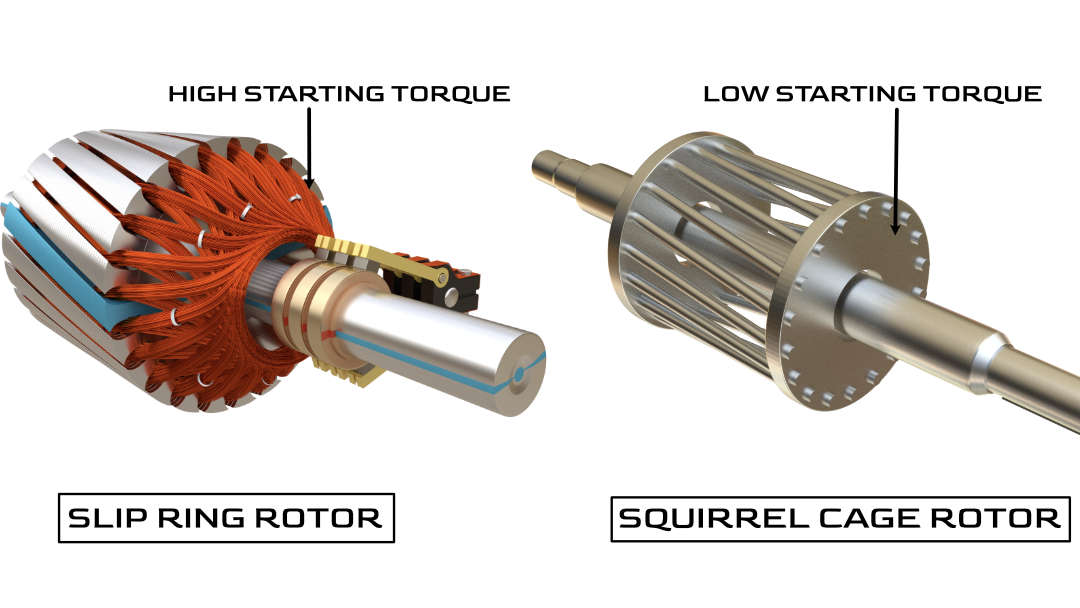
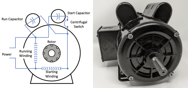
STARTING METHODS: Induction MotorsAlso known as asynchronous motors, these are the most common types of AC motors. Induction motors operate on the principle of electromagnetic induction, where the rotating magnetic field of the stator induces a current in the rotor. This category can be further divided into:
Synchronous MotorsSynchronous motors operate at a constant speed, regardless of the load, synchronizing with the frequency of the supply current. The rotor speed is directly proportional to the frequency of the supply current. Types include:
Single-Phase MotorsDesigned for single-phase power supply, these motors are typically used in domestic appliances and small machinery. They include:
Variable Frequency Drives (VFD) MotorsThough not a separate category of motors, VFDs are crucial in controlling the speed of AC motors. By varying the frequency and voltage supplied to the motor, VFDs allow precise control of motor speed, enhancing efficiency and control in applications ranging from industrial machinery to HVAC systems. Specialized AC MotorsThis category includes motors designed for specific applications, such as:
AC Motor EquationsThe formula for an induction motor primarily relates to its basic operation, performance characteristics, and efficiency. Induction motors operate based on the principle of electromagnetic induction, where a rotating magnetic field is produced by the stator (stationary part), inducing a current in the rotor (moving part), which creates another magnetic field that interacts with the stator field to produce torque. Synchronous speedOne key formula for an induction motor is the calculation of the synchronous speed \( \large N_{s} \), which is the speed of the rotating magnetic field in the stator: Synchronous Speed: \( \large \hspace{10 mm}\Large N_{s}= \frac{120f}{p} \)
Where:
Slip EquationAnother important set of equations relates to the slip (\( \Large\textbf{s} \) ), which is the difference between the synchronous speed and the actual rotor speed, expressed as a percentage of the synchronous speed: \( \large \hspace{10 mm}\Large s = \Large\frac{N_{s}- N_{r} }{N_{s}} \)
Where:
The actual speed of the rotor ( \( \textbf{N}_{\textbf{r}} \)) can be calculated as: \( \large \hspace{10 mm}\Large N_{r} = N_{s} (1-\Large\frac{s}{100}) \) TorqueThe torque ( \( \textbf{T} \)) produced by an induction motor can be approximated by the formula: \( \large \hspace{10 mm}\Large \textbf{T}=\Large \frac{9.55 \times P_{out}}{N_{r}} \)
Where:
EfficiencyEfficiency( \( \eta \)) of an induction motor is defined as the ratio of output power to input power, usually expressed as a percentage: \( \large \hspace{10 mm}\Large \eta =\Large \frac{P_{out}}{P_{in}} \times 100 \)
Where: Medium Voltage EquipmentMedium voltage equipment evaluation has two components: momentary and interrupting ratings. The momentary rating is the asymmetrical current seen ½ cycle after the fault occurs. The interrupting rating reflects the fault duties at the time when a protective device will operate to clear a fault (typically 2, 3, 5 or 8 cycles). ANSI allows a simplified momentary rating calculation of 1.6 times the symmetrical fault duty. The actual value is calculated as follows.
\( I_{asym \frac{1}{2}cycle}= I_{rms-sym} x \sqrt{1+2e^{\frac{-2\pi} {\frac{X} {R}} \times C} } \)
\({C}\)\(\text{= is the first} \frac{1}{2}cycle\) Equipment Rating EvaluationThe purpose of the equipment evaluation is to compare the maximum calculated short-circuit currents to the short-circuit ratings of protective devices or the withstand rating of an enclosure. The Device Evaluation Report, located in the appendix of the project report, provides a summary of fault duties. It compares these duties, factoring in ANSI multipliers, with equipment ratings for each location within the modeled system. This comparison aims to determine whether the device is capable of either interrupting or withstanding the fault currents present in the electrical system where it's applied. 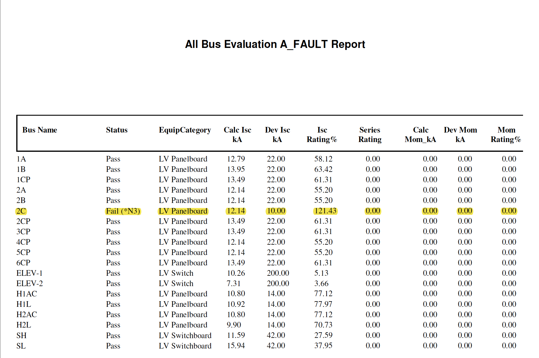
Bus Name
Status
Equipment Category
Calc Isc_kA
Dev Isc_kA
Isc Rating%
Series Rating
Calc Mom_kA
Dev Mom_kA
Mom Rating% |
||||||||||||||||||||||||||||||||||||||||||||||||||||||||||||||||||||||||||||
| Power Transformers | |
|---|---|
|
|
|
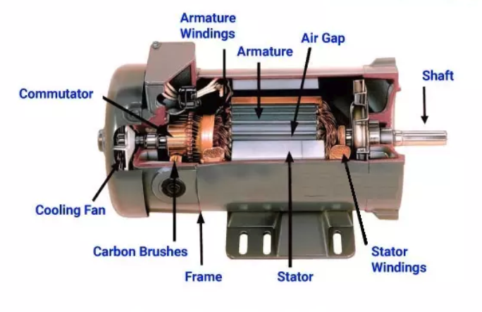
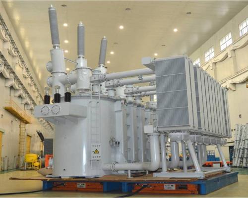
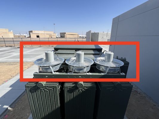
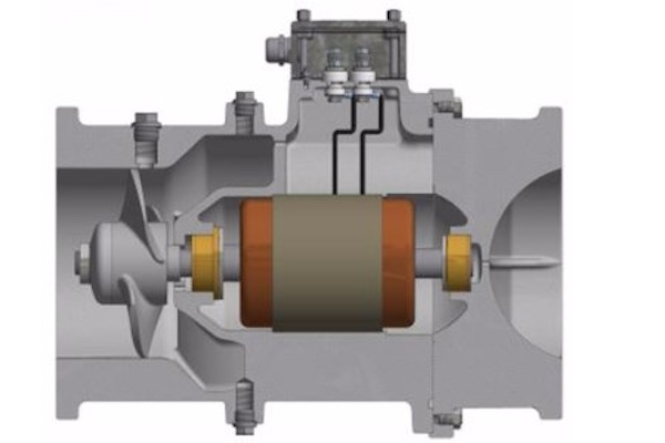
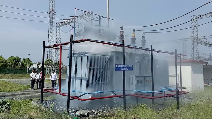
Transformer Current calculatorPower TransformersElectrical power transformers come in various types, each categorized based on its construction, operation, application, and cooling methods. Every type is designed to serve a unique purpose within the electrical power system, ranging from stepping voltage levels up or down, isolating circuits, to managing phase shifts. The following structured outline provides an overview of the main categories and specific types of transformers, highlighting their distinct functions and applications. What is a Transformer?A transformer is an electrical apparatus designed to convert alternating current from one voltage to another. It can be designed to "step up" or "step down" voltages. How Does a Transformer Work?A transformer works on the magnetic induction principle. It has no moving parts and is a completely static solid state device, which insures, under normal operating conditions, a long and trouble-free life. It consists, in its simplest form, of two or more coils of insulated wire wound on a laminated steel core. When voltage is introduced to one coil, called the primary, it magnetizes the iron core. A voltage is induced in the other coil, called the secondary or output coil. The change of voltage (or voltage ratio) between the primary and secondary depends on the turns ratio of the two coils. Station Transformers
Definition:
Application:
Characteristics: 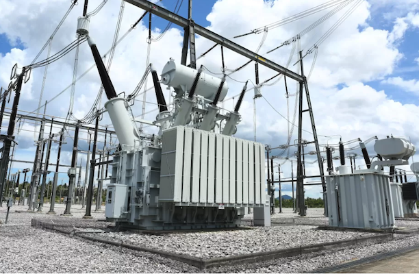
Distribution TransformersUsed to step down voltage for distribution to residential or commercial users.
Application:
Characteristics: 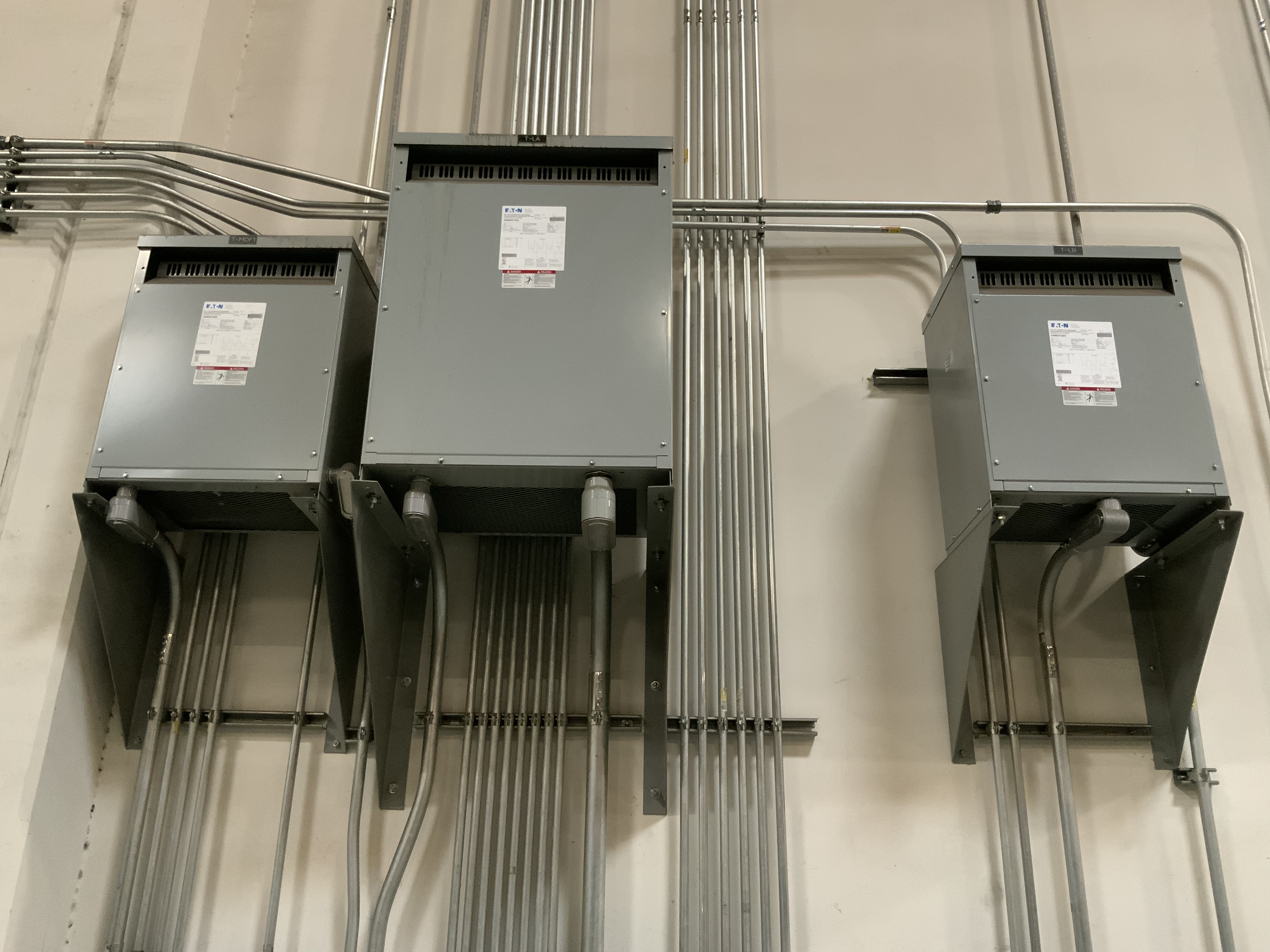
Instrument Transformers
Current Transformer (CT) 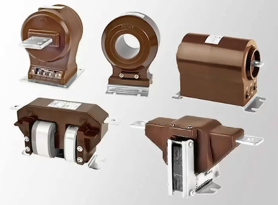
Potential Transformers (PT, VT, CPT)These transformers are also used to step down high voltage to a safer, measurable level. They are utilized for metering and protection by providing an accurate voltage measurement. 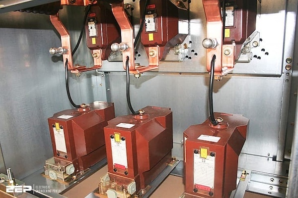
Can Transformers be Operated at Voltages other than Nameplate Voltages?ANSWER: In some cases, transformers can be operated at voltages below the nameplate rated voltage. In NO case should a transformer be operated at a voltage in excess of its nameplate rating unless taps are provided for this purpose. When operating below the rated voltage the KVA capacity is reduced correspondingly. For example, if a 480 volt primary transformer with a 240 volt secondary is operated at 240 volts, the secondary voltage is reduced to 120 volts and if the transformer were originally rated 10 KVA, the reduced rating would be 5 KVA, or in direct proportion to the applied voltage. Is it Possible to Change Three Phase to Two Phase or Vice-Versa with Standard Transformers?
ANSWER:
Yes. This is a very practical application for standard
single phase off-the-shelf transformers. Some typical voltage
combinations are as follows: Can Transformers Develop Three Phase Power from a Single Phase Source?ANSWER: No, phase converters or phase shifting devices such as reactors and capacitors are required to convert single phase power to three phase. Can Transformers be Used in Parallel?ANSWER: Single phase transformers can be used in parallel only when their impedances and voltages are equal. If unequal voltages are used a circulating current exists in the closed network between the two transformers which will cause excessive heating and result in a shorter life of the transformeer. In addition, impedance values of each transformer must be within 7½ % of each other. EXAMPLE: Transformer A has an impedance of 4%, transformer B which is to be parallel to A must have an impedance between the limits of 3.7% and 4.3%. When paralleling three phase transformers the same precautions must be observed as listed above, plus the angular displacement and phasing between the two transformers must be identical. Can 60 Hz Transformers be Operated at 50 Hz?ANSWER: Some transformers rated below 1 KVA can be utilized on 50 Hz service. Normally, Transformers 1 KVA and larger, rated at 60 Hz, should not be used on 50 Hz service due to the higher losses and resultant heat rise; special designs are required for this service. How Can 60 Hz Transformers be Used at Higher Frequencies?ANSWER: Normally, transformers can be used at frequencies above 60 Hz up through 400 Hz with no limitations provided nameplate voltages are not exceeded. However, 60 Hz transformers will have less voltage regulation at 400 Hz than at 60 Hz. Where better regulation and smaller physical size are required, contact the factory for special 400 Hz designs. Before doing so, you should always consult the manufactures for additional information. What is Meant by Regulation in a Transformer?ANSWER: Voltage regulation in transformers is the difference between the no load voltage and the full load voltage. This is usually expressed in terms of percentage. For example: A transformer delivers 100 volts at no load and the voltage drops to 9.5 volts at full load, the regulation would be 5%. Dry type distribution transformers generally have regulation from 2% to 4%, depending on the size and the application for which they are used. Power TransformersElectrical power transformers come in various types, each categorized based on its construction, operation, application, and cooling methods. Every type is designed to serve a unique purpose within the electrical power system, ranging from stepping voltage levels up or down, isolating circuits, to managing phase shifts. The following structured outline provides an overview of the main categories and specific types of transformers, highlighting their distinct functions and applications. Frequently Asked QuestionsQuestion 1:Should I put Maintenance Mode Incident Energy Values on arc flash labels?Answer:Over the past decade, electrical equipment manufacturers have introduced products featuring a "Maintenance Mode." This setting allows users to temporarily adjust the trip time of relays or low-voltage circuit breaker trip units, enabling them to respond more quickly and reduce arc flash hazards on the protected bus. Users can activate this mode via a switch on the front panel or an electrical control signal sent to the back of the panel. This method of hazard reduction is preferred over simply increasing the level of personal protective equipment (PPE) for workers exposed to higher energy levels. Since it is considered a form of hot work, the relevant information should not appear on a label. Instead, the maintenance procedure, appropriate PPE, and instructions for using the Maintenance Mode feature should be officially approved and included in the Hot Work Permit. Transformer EquationsOne key formula for an induction motor is the calculation of the synchronous speed \( \large N_{s} \), which is the speed of the rotating magnetic field in the stator: \( \Large Turns Ratio= \huge \frac{N_{1}}{N_{2}} \) \( \huge \frac{N_{1}}{N_{2}} = \frac{V_{L1}}{V_{L2}} \) \( \huge\frac{N_{1}}{N_{2}} = \frac{I_{L2}}{I_{L1}} \)
Where:
Full load Amps (3 phase)\( \Large FLA_{pri} = \huge \frac{VA}{ \sqrt{3} \times V_{L1} } \) Full load Amps (Single Phase)\( \Large FLA_{pri} = \huge \frac{VA}{ V_{L1} } \)
\( \Large VA\) : is the apparent power rating of the transformer in VA or kVA. Transformer Short Circuit Current
|
|


| Transformer Videos | |
|---|---|
|
|
|