Ground Fault Inspection Testing
Global Power Services is certified to conduct GFI inspections in Los Angeles and San Diego County and surrounding areas. Los Angeles and San Diego County requires testing companies or laboratories to be certified with their respective department of building and safety, to perform ground fault equipment testing and calibration.

Los Angeles
County
Department of
Public Works
Building and Safety Division
900 S. Fremont Avenue
Alhambra, CA 91803

San Diego County
Department of Building and Safety
5201 Ruffin Road
San Diego, California, 92123
858-565-5920
NEC Testing Requirements
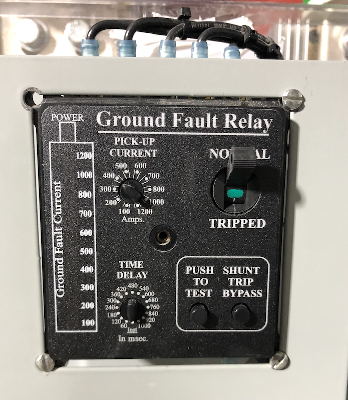
The National Electrical Code® (NEC® ) has specific ground fault equipment protection requirements in 215.10, 230.95, 240.13 and 517.17. Ground fault relays (or sensors) are used to sense low magnitude ground faults. When the ground fault current magnitude and time reach the G.F. relay pick up setting, the control scheme signals the circuit disconnect to open.
NEC 70, Article 230.95
Ground-Fault
Protection of Equipment
Ground-fault protection of equipment shall be provided for solidly grounded wye electric services of more than 150 volts to ground but not exceeding 1000 volts phase-to-phase for each service disconnect rated 1000 amperes or more. The grounded conductor for the solidly grounded wye system shall be connected directly to ground through a grounding electrode system, as specified in 250.50, without inserting any resistor or impedance device.
The rating of the service disconnect shall be considered to be the rating of the largest fuse that can be installed or the highest continuous current trip setting for which the actual overcurrent device installed in a circuit breaker is rated or can be adjusted.
NEC 70, Article 517.17
Ground-Fault
Protection
(C) Selectivity. Overcurrent Ground-fault protection for operation of the service and feeder disconnecting means sh all be fully selective such that the feeder device, but not the service device, shall open on ground faults on the load side of the feeder device. Separation of ground-fault protection time-current characteristics shall conform to manufacturer’s recommendations and shall consider all required tolerances and disconnect operating time to achieve 100 percent selectivity.
(D) Testing. Overcurrent When equipment ground-fault protection is first installed, each level shall be performance tested to ensure compliance with 517.17(C).
| Ground Fault Protection (GFI) | |
|---|---|
Ground Fault Protection (GFP)
Description:
How Does it Work:
GFCI: 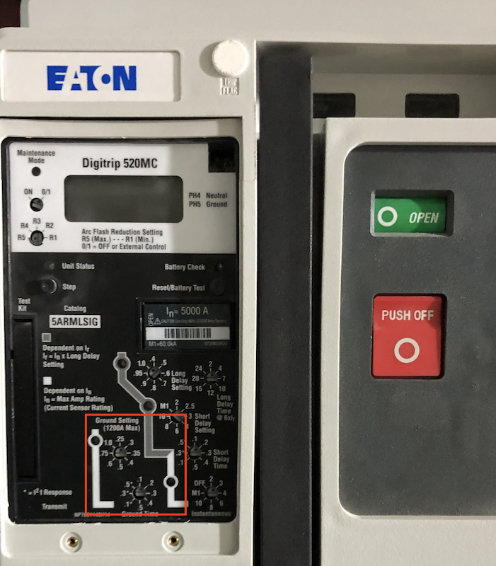
Test ProcedureVisual and Mechanical Inspection:
Insulation Test:
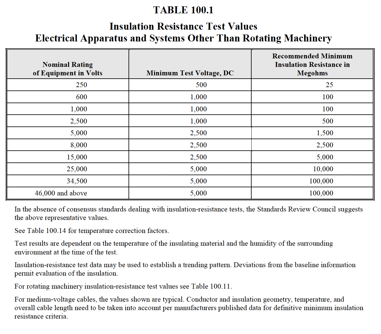
NETA Table 100.1 shows recommended minimum test result valuesContact Resistance Test:
Electrical Test Procedure
Low Voltage Circuit Breaker Ground Fault Sensing
Current Transformers (CTs):
Electronic Trip Unit: The electronic trip unit uses the residual method, calculating the vector sum of the currents measured by the CTs. In a balanced, no-fault condition, this sum should be zero. \( \Large I_{a}+I_{b}+I_{c} = I_{n} \) \( \Large I_{a}+I_{b}+I_{c}- I_{n} = 0\) 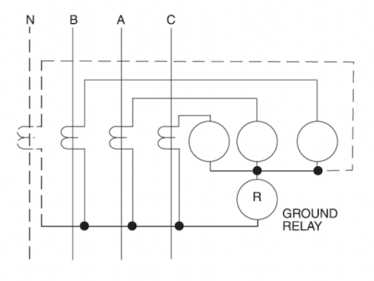
trip units allow for adjustment of the ground fault detection settings, including the trip threshold and delay. These settings can be finely tuned to balance between sensitivity (to quickly detect and respond to real faults) and selectivity (to avoid nuisance tripping from transient imbalances or non-hazardous events). The ground fault pickup settings are usually a multiple of the current sensor rating (CT or ln), in steps of 0.1 xCT. The maximum GF pickup value is limited to 1200 A per UL standard.
Trip Mechanism Activation: 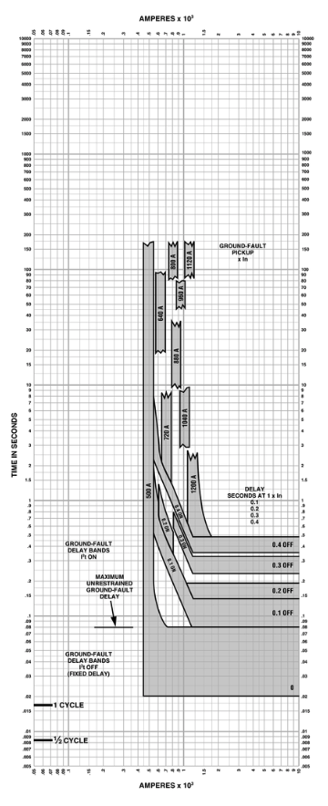
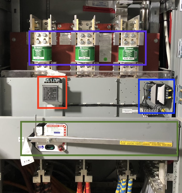
Common Breaker GFI FailuresReverse Polarity (Residual System)Reverse polarity in current transformers (CTs) can indeed arise from two main scenarios: A physically flipped CT or the reversed secondary wiring connections . Both scenarios disrupt the accurate sensing and measuring of currents, which are critical for protection devices like circuit breakers to function correctly. Here’s a breakdown of how each can cause reverse polarity:
Direction of Current The P1 terminal should face towards the incoming power source, which means that current enters the CT from this side. The P2 terminal should face towards the load, indicating the direction in which the current exits the CT. In a properly installed ground fault system, both phase current and neutral return current vectors summing up to equal zero \( \Large I_{a}+I_{b}+I_{c}= I_{n} \) \( \Large I_{a}+I_{b}+I_{c}- I_{n} = 0 \) In a system with a flipped CT or reversed neutral CT polarity, both phase current and neutral return current vectors will sum up to a non-zero sum value even in a fault-free conditions or cause a zero-sum when a fault exists \( \Large I_{a}+I_{b}+I_{c}+ I_{n} \ne 0 \) Bonding Jumper
Purpose
NEC 70E-2024, 250.30(A)(1)(b)
Purpose
Ineffective Neutral Current Path 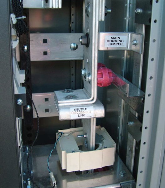
|
|
| NETA Test Procedure | |
|---|---|
Ground-Fault Protection Systems, Low-VoltageAcceptance TestingA. Visual and Mechanical Inspection
B. Electrical Tests
C. Test Values – Visual and Mechanical
D. Test Values – Electrical
Ground-Fault Protection Systems, Low-VoltageMaintenance TestingA. Visual and Mechanical Inspection
B. Electrical Tests
C. Test Values – Visual and Mechanical
D. Test Values – Electrical
NETA
ATS / MTS
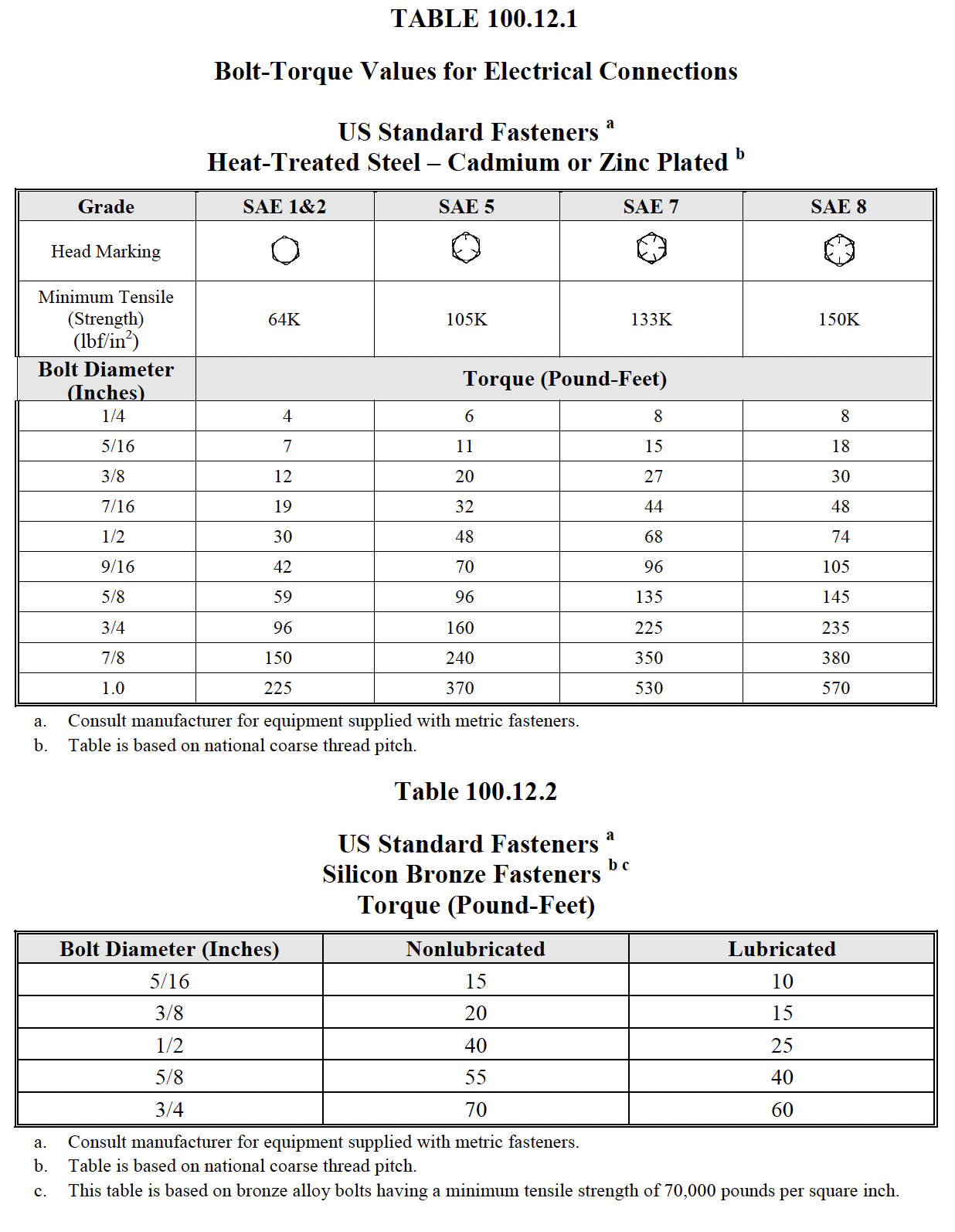
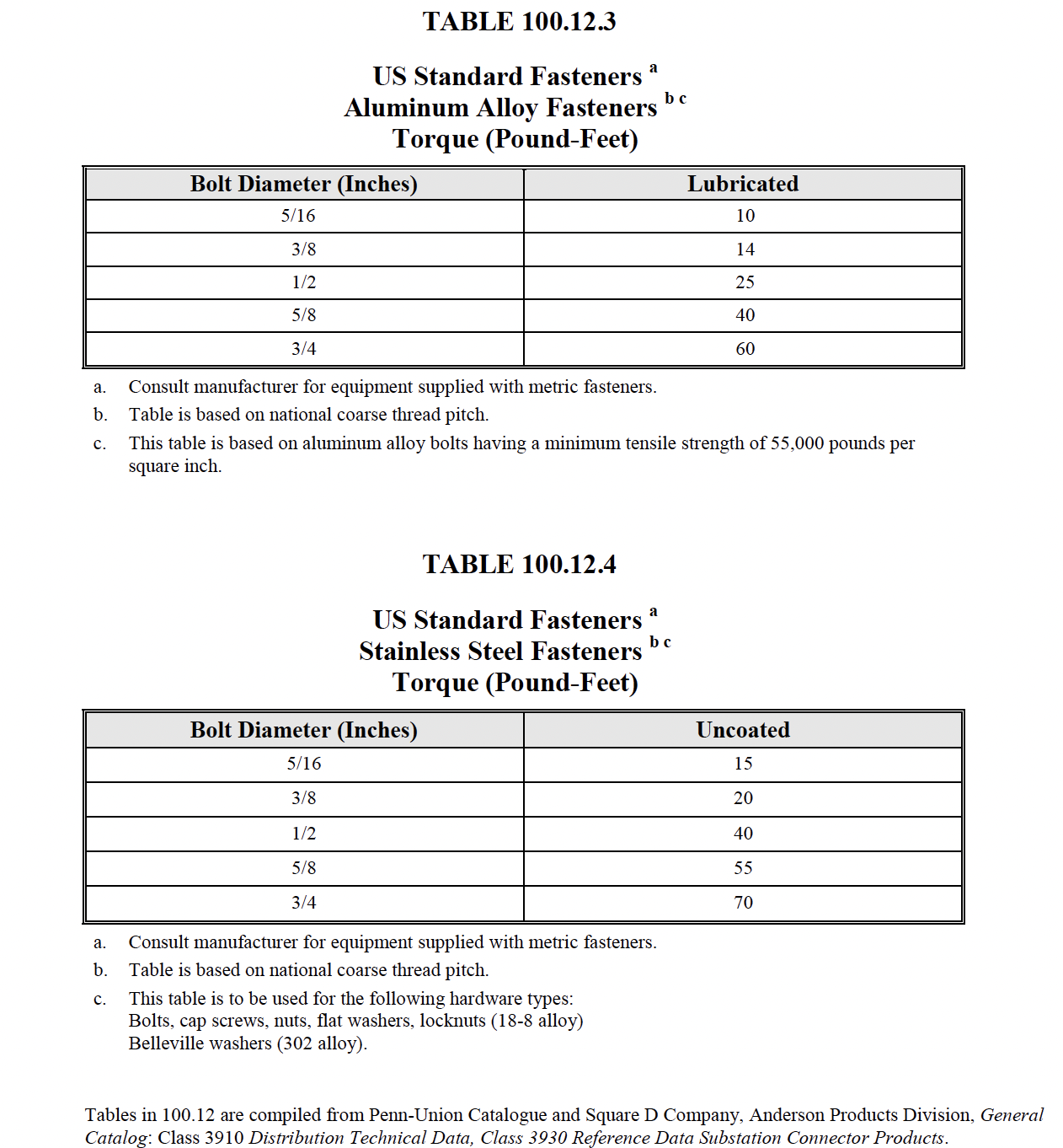
TABLE
100.12
|
|