Ground System Testing
Global Power Services provides comprehensive ground testing and diagnostic solutions. Our testing services are designed to pinpoint electrical grounding issues, mitigate potential hazards, enhance system performance, and safeguard valuable equipment.
Regular earth ground testing is essential for maintaining the safety and efficiency of electrical systems. It is advised to conduct earth ground testing on a routine basis to:
- During the initial installation of electrical systems to verify that proper grounding has been established.
- After any modifications or additions to the electrical system that could affect grounding.
- Periodically as part of routine maintenance procedures to ensure continued effectiveness.
- Whenever there are signs of electrical problems or equipment malfunction that could be related to grounding issues.
National Electrical Code Test Requirements
Electrode Test (Ground Rod / Ufer)
NEC 70, Article 250.53, A(2) states that a single electrode with a resistance to ground greater than 25Ω shall be augmented by one additional electrode. Although the NEC has a maximum requirement of 25 ohms, some facilities with sensitive electronic equipment may require their grounding system to have a resistance value as low as 1 ohm.
NEC 70-2023
250.53 Grounding Electrode System Installation
(A) Rod, Pipe, and Plate Electrodes.
Rod, pipe, and plate electrodes shall be free from non-conductive coatings such as paint or enamel.
Rod, pipe, and plate electrodes shall meet the requirements of 250.53(A)(1) through (A)(3).
- Below Permanent Moisture Level
If practicable, rod, pipe, and plate electrodes shall be embedded below permanent moisture level. - Supplemental Electrode Required
A single rod, pipe, or plate electrode shall be supplemented by an additional electrode of a type specified in 250.52(A)(2) through (A)(8). The supplemental electrode shall be permitted to be bonded to one of the following:- Rod, pipe, or plate electrode
- Grounding electrode conductor
- Grounded service-entrance conductor
- Nonflexible grounded service raceway
- Any grounded service enclosure
Below Exception: If a single rod, pipe, or plate grounding electrode has a resistance to earth of 25 ohms or less, the supplemental electrode shall not be required.
- Supplemental Electrode
If multiple rod, pipe, or plate electrodes are installed to meet the requirements of this section, they shall not be less than 1.8 m (6 ft) apart.
Crane Grounding
Grounding requirements for cranes generally fall under OSHA's electrical safety standards, and cranes must be grounded to prevent electrical hazards. The specific grounding requirements may depend on the type of crane, the location where it is used, and other factors. Here are some general guidelines:

-
Grounding for Overhead Cranes:
Overhead cranes, which are typically used in industrial settings, should also be grounded to prevent electrical hazards. Grounding methods can include grounding conductors and ground fault protection devices. -
Grounding for Mobile Cranes:
Mobile cranes, such as lattice boom and hydraulic cranes, should begrounded to prevent the buildup of static electricity and to provide a path for electrical faults to safely dissipate. This may involve using grounding cables and rods connected to the crane. -
Grounding in Hazardous Locations:
In hazardous locations, such as those with flammable gases or vapors, additional grounding requirements may apply to prevent explosions. These requirements are often more stringent and can involve specialized equipment. -
Inspection and Maintenance:
Regular inspection and maintenance of grounding systems are essential to ensure they are effective. Cranes should be inspected for loose or damaged grounding connections, and any issues should be promptly addressed.

| Grounding Test Procedures | |
|---|---|
Purpose of GroundingGrounding of electrical equipment serves several purposes:
Accurate measure of a facility's ground resistance is essential in preventing costly downtime due to service interruptions caused by poor grounds. 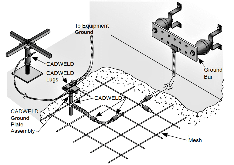
Grounding System ConstructionSoil Resistivity Test (4-Point Test)Soil resistivity directly impacts the resistance or performance of an electrical grounding system. It is also the starting point of any electrical grounding design. Prior to installing a ground system the resistivity of the surrounding soil should be measured. The 4-point methode is used for to measure the soils resistivity. Several soil measurements are taken at different locations throughout the surface area where the future structure will be placed. Several different locations are chosen because soil resistivity can vary throughout the site area 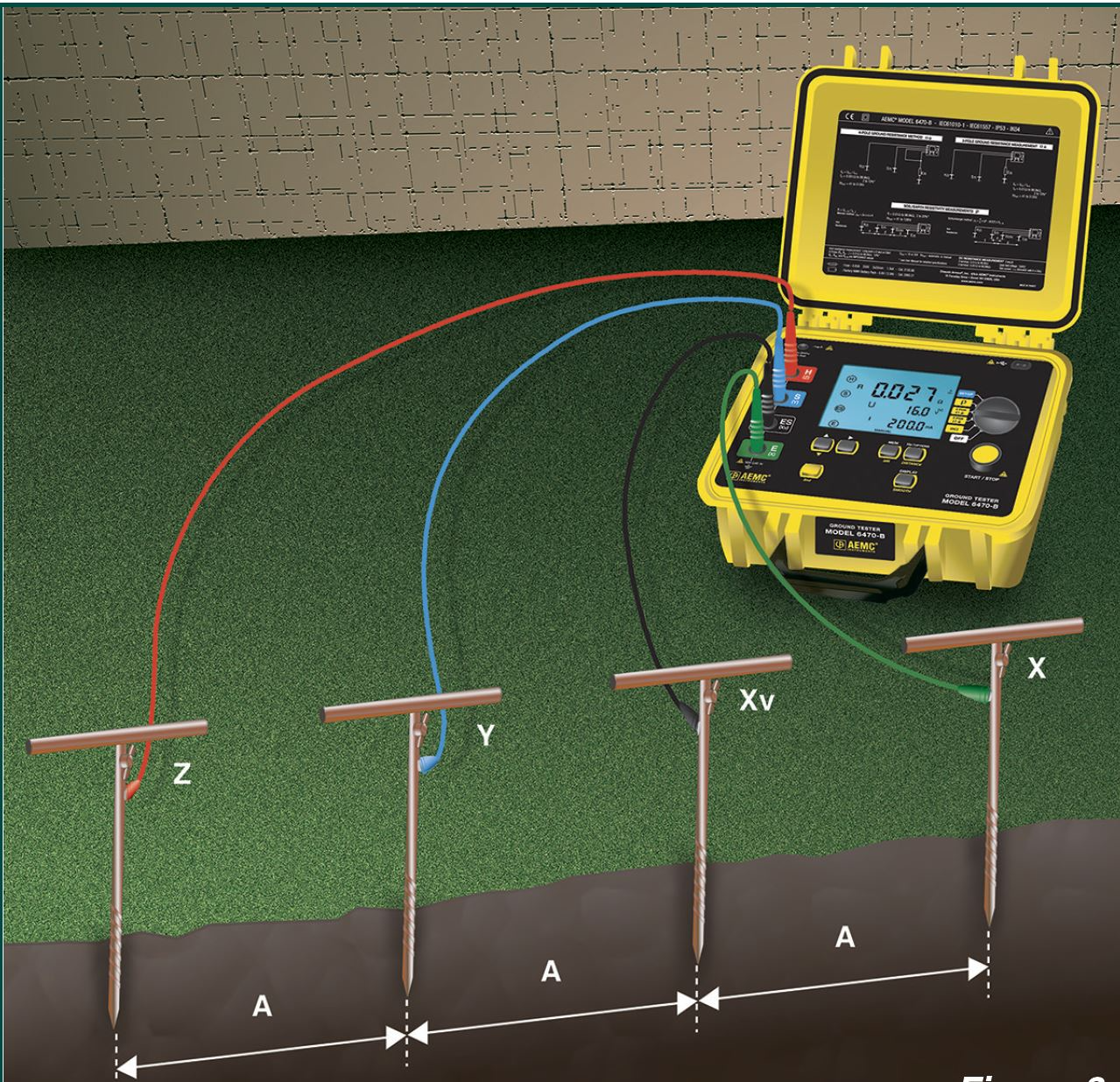
Grounding System DesignA well designed ground system ensures that protective devices will operate correctly during a fault event and reduce any excessive voltages developed during a fault, which could damage equipment and endanger the safety of anyone near the fault. Inaccurate resistivity tests can lead to unnecessary costs in additional system design and construction costs. Grounding System TestingAfter installation it is vital to check that the electrical grounding system meets the design criteria and should be measured periodically to ensure corrosion or changes in the soil's resistivity do not have an adverse effect. Ground networks may not appear faulty until a fault occurs and a dangerous situation arises. Test ProceduresVisual and Mechanical Inspection:
Grounding Test Procedure:There are three basic test methods, Fall-of-Potential method (three-point test), Dead Earth method (two-point test), and Clamp-on test method.
Test ResultsThere is a good deal of confusion as to what constitutes a good ground and what the ground resistance value needs to be. Ideally a ground should be of zero ohms resistance.
National Electrical Code Maximum Values For instance, the telecommunications industry has often used 5.0 ohms or less as their value for grounding and bonding. The goal in ground resistance is to achieve the lowest ground resistance value possible that makes sense economically and physically.
We recommend that continuity and resistance of grounding systems
shall be tested immediately after installation, repair, and modification;
and annually thereafter.
Resistance to earth can vary with changes in climate and temperature. Such changes can be considerable. An earth electrode that was good (low-resistance) when installed may not stay that way; to be sure, you must check it periodically. Soil Resistivity (4-Point Test):Measurements of earth resistivity are useful for finding the best location and depth for low resistance electrodes. Such studies are made, for example, when a new electrical unit is being constructed; a generating station, substation, transmission tower, or telephone central office. In addition, earth resistivity may be used to indicate the degree of corrosion to be expected in underground pipelines for water, oil, gas, gasoline, etc. In general, spots where the resistivity values are low tend to increase corrosion. This same kind of information is a good guide for installing cathodic protection. 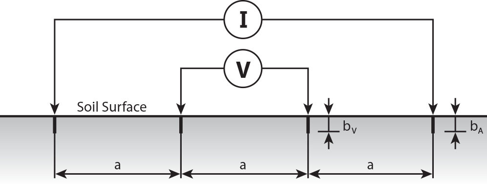
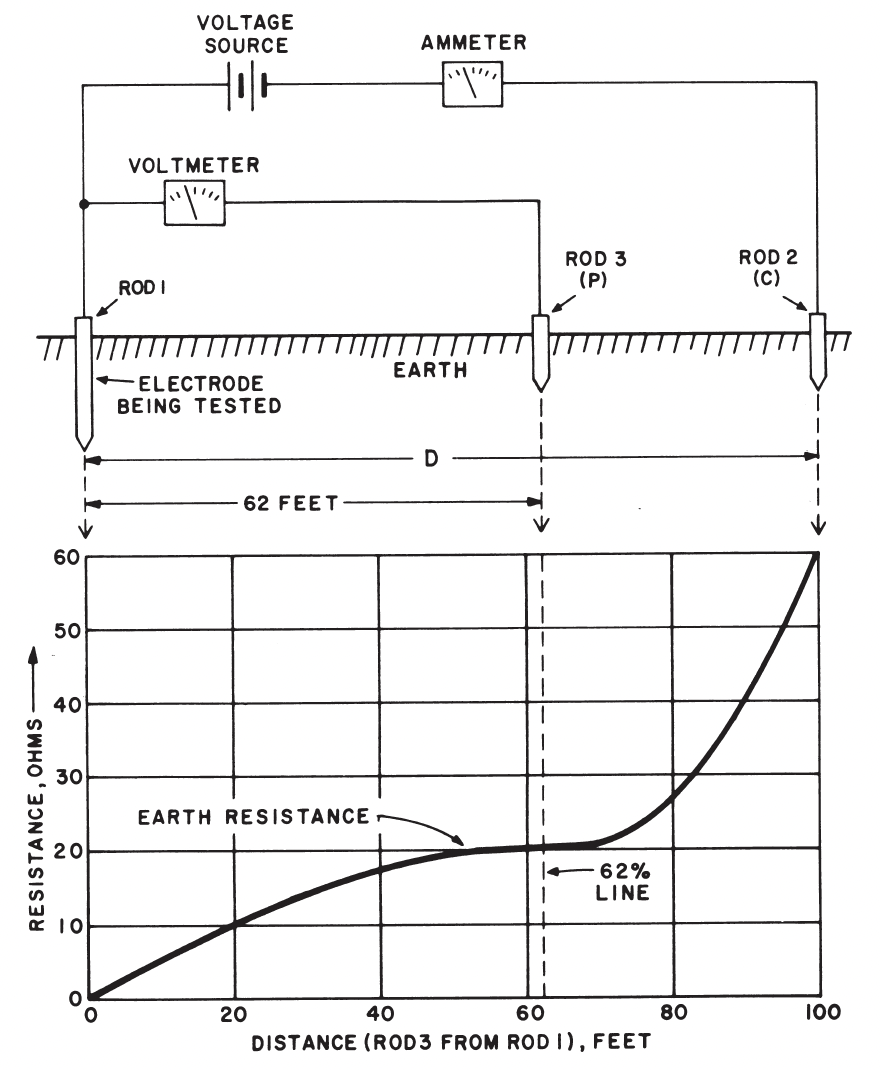
Fall of Potential3-Point Test ProcedureThe Fall of Potential test, also known as the 3-point ground resistance test, is a method used to measure the resistance of an earth grounding electrode or rod to ensure that it is adequate to safely conduct fault currents to the ground. This method is critical for ensuring the safety and effectiveness of grounding systems in electrical installations. The process involves three points: the ground electrode under test, a reference ground electrode placed a significant distance away from the test electrode (usually tens of meters away, depending on the electrode size and soil conditions), and a third auxiliary electrode placed between them.
\({R_{A}} =\frac{R_{1} +R_{2}+R_{3} }{3} \)
Two-Point Ground Resistance Test:The two-point ground resistance test involves using a resistance meter to measure the resistance between two points in the grounding system. This method typically requires disconnecting the ground system to isolate it from the electrical system it serves. One lead of the meter is connected to the earth ground rod or connection point, and the other lead is connected to a separate point in the ground system or to another grounding rod. The meter then passes a current through the circuit formed between the two points, and the resistance is measured. Clamp-On Ground Testing Method:A clamp-on ground resistance test is a method used to measure the resistance of an electrical grounding system without the need to disconnect the ground rod or system from the equipment it serves. This type of test is performed using a clamp-on ground resistance tester, a specialized instrument that can measure ground resistance through inductive testing. The process is non-intrusive, making it a safe and convenient option for checking the integrity and effectiveness of grounding systems in various electrical installations. Clamp-on ground resistance testers are widely used for routine maintenance checks and troubleshooting in electrical installations to ensure that grounding systems meet safety standards and regulations. They help in identifying potential grounding issues that could compromise the safety and reliability of electrical systems, such as high ground resistance values that may indicate poor grounding connections or deteriorated ground rods. 
IEEE Standards
|
|
| NETA Test Procedure | |
|---|---|
NETA ATS-20177.13 Grounding SystemsA. Visual and Mechanical Inspection:
B. Electrical Tests:
C. Test Values – Visual and Mechanical
D. Test Values – Electrical
NETA MTS7.13 Grounding SystemsA. Visual and Mechanical Inspection:
B. Electrical Tests:
C. Test Values – Visual and Mechanical
D. Test Values – Electrical
NETA ATS / MTS
|
|
| Grounding Video | |
|---|---|
|
|
|