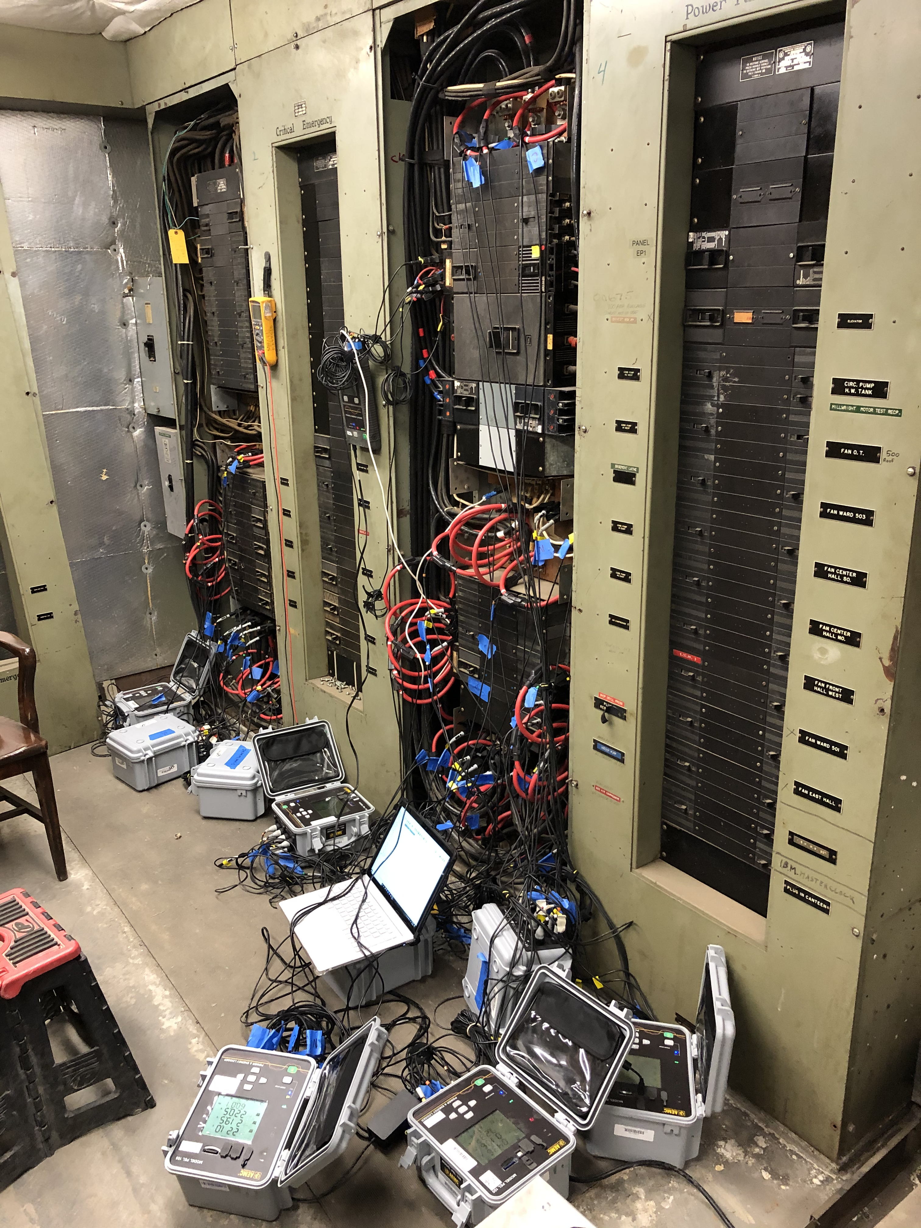
Electric Load Monitoring
Electric load monitoring, crucial for electrical system efficiency and safety, involves these key aspects:
- Verifies system capacity: Confirms the electrical system can handle the current and future loads.
- Optimizes power usage:. Helps in minimizing wasteful power consumption.
- Identifies overloads: Detects when the system is overloaded, preventing potential failures.
- Detects issues such as harmonic disturbances and poor power factor: Identifies issues that could affect system performance and equipment longevity.
- Facilitates Facility Management: Aids in expansions, renovations, and solving operational problems through measured data over time.
Process: Involves measuring electrical load characteristics over time with specialized equipment.
| Power Quality | |
|---|---|
Power Quality StudiesPower quality refers to the degree to which the electrical power supplied to devices and systems meets their operational requirements. It encompasses various aspects such as voltage stability, frequency stability, and the purity of the sinusoidal waveforms. Power quality is crucial for a facility for several interconnected reasons, directly impacting operational reliability, equipment lifespan, safety, and financial performance. The significance of maintaining high power quality encompasses:
Equipment Efficiency and Longevity:
Safety:
Energy Efficiency:
Data Integrity:
Operational Reliability:
Compliance with Standards and Regulations:
Cost Savings:
Enhanced Facility Performance: Common Power Quality Problem:
Voltage Sags (Dips):
Voltage Swells: Mathematically, if \( \Large \ V_{nom} \) is the nominal voltage, a sag or swell can be represented as a deviation, where \( \Large \ V_{actual} \) is the actual voltage during the event: \( \Large Deviation(\%) = \frac{V_{actual}-V_{nom}}{V_{nom}} \times 100\% \)
Voltage Imbalance:
Harmonics:
Transients(Spikes/Surges):
Frequency Variations: Introduction to Harmonic DistortionBefore the 1960s, electrical systems rarely encountered issues with harmonic distortion. The advent of digital electronics, marked by the digital switching of signals such as voltage, brought harmonic distortion to the forefront. Devices like computers and printers, known as non-linear loads, disrupt electrical systems by producing harmonics. Non-linear LoadsIn a typical AC power system, current flows sinusoidally at a certain frequency, usually 50 or 60 Hz. Connection of linear devices to the system results in current draw at the voltage frequency. Non-linear devices, however, lead to the generation of non-sinusoidal waveforms. These are constructed by superimposing sine waves at different frequencies, known as "Harmonics." Non-linear loads not only produce harmonics but also significantly alter the current waveform, leading to complex interactions within the system. As of 2020, 75% off all electrical loads in North America operate with non-linear loads. Sources of Harmonics
Effects of Harmonics
DefinitionHarmonics have frequencies that are integer multiples of a waveform's fundamental frequency. Harmonic distortion is the degree to which a waveform deviates from it’s pure sinusoidal values as a result of the summation of a harmonic elements. Harmonics are represented by their order \( \Large n\) related to the fundamental frequency \( \Large f\) with their amplitude \(\Large A_{n}\) and phase \(\Large \phi_{n}\) , given by: \(\Large V_{t} = V_{0} +\sum_{n=1}^{\infty } A_{n} \sin(2n\pi ft + \phi_{n})\)
Maximum Total Harmonic Distortion (THD)IEEE 519, Recommended Practice and Requirements for Harmonic Control in Electrical Power Systems, establishes limits for harmonic distortion and provides guidelines for harmonic control in electrical power systems. It defines limits for Total Harmonic Distortion (THD) for voltage and current waveforms. These limits are defined at the Point of Common Coupling (PCC). Point of Common Coupling (PCC)
PCC is defined as the point in the power system closest to the user where the system, owner or operator
could offer service to another user. Frequently for service to industrial users ( i.e. manufacturing plants)
via a dedicated service transformer, the PCC is at the high voltage side of the transformer. The PCC is basically recognized at the point where it any harmonics could migrate onto the utility system and cause problems for other customers. The intention of having a point of common coupling is to prevent high levels of harmonics generated by one customer from causing distortion to other customers on the power grid. In considering the primary site of the transformer (that supplies, one customer), the transformer's impedance will decrease the short circuit ratio. This result in an increase in the harmonic current limits. The voltage distortion will be higher at the secondary side of the transformer. Total Harmonic DistortionIEEE 519 recommends that the THD in the voltage waveform should not exceed 5%for general systems. It's important to note that specific limits can vary depending on the system voltage and the point of common coupling (PCC).
For Current THD: Harmonic Mitigation
3rd Order HarmonicMost Harmonic problems are caused by the 3rd harmonic. Each phase in a three-phase system is 120 degree apart.the third harmonic s between the phases add together, which leads to oscillating currents. 3rd Harmonic EffectsIncreased Neutral Current: In three-phase systems, the 3rd and multiples of 3rd harmonics (like 9th, 15th) are in phase and add up in the neutral conductor. This can result in neutral current being significantly higher than the phase currents, potentially exceeding the capacity of the neutral conductor and leading to overheating.
Interference in Communication Lines:
Overheating of Electrical Components:
Reduced Efficiency of Energy Conversion Devices:
Tripping of Circuit Breakers and Blown Fuses:
Adverse Effects on Power Factor:
Damage and Malfunction of Equipment: |
|